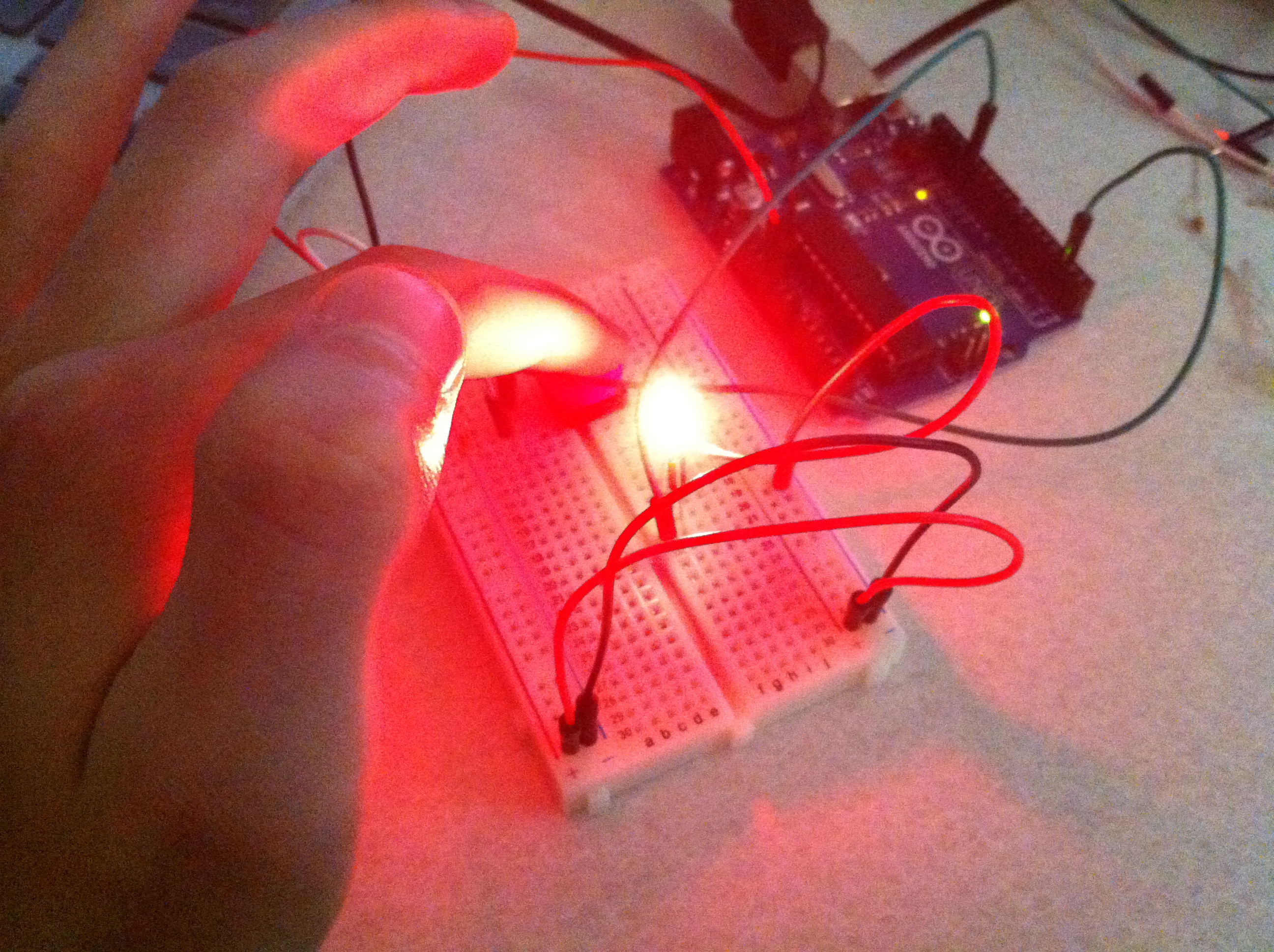
With the help of Marco and Shubs, we were able to make a working pull up circuit! By connecting an LED to pin 13 and creating a pull up circuit that fed to pin 2, we were able to successfully run the Arduino digital “button” example sketch.

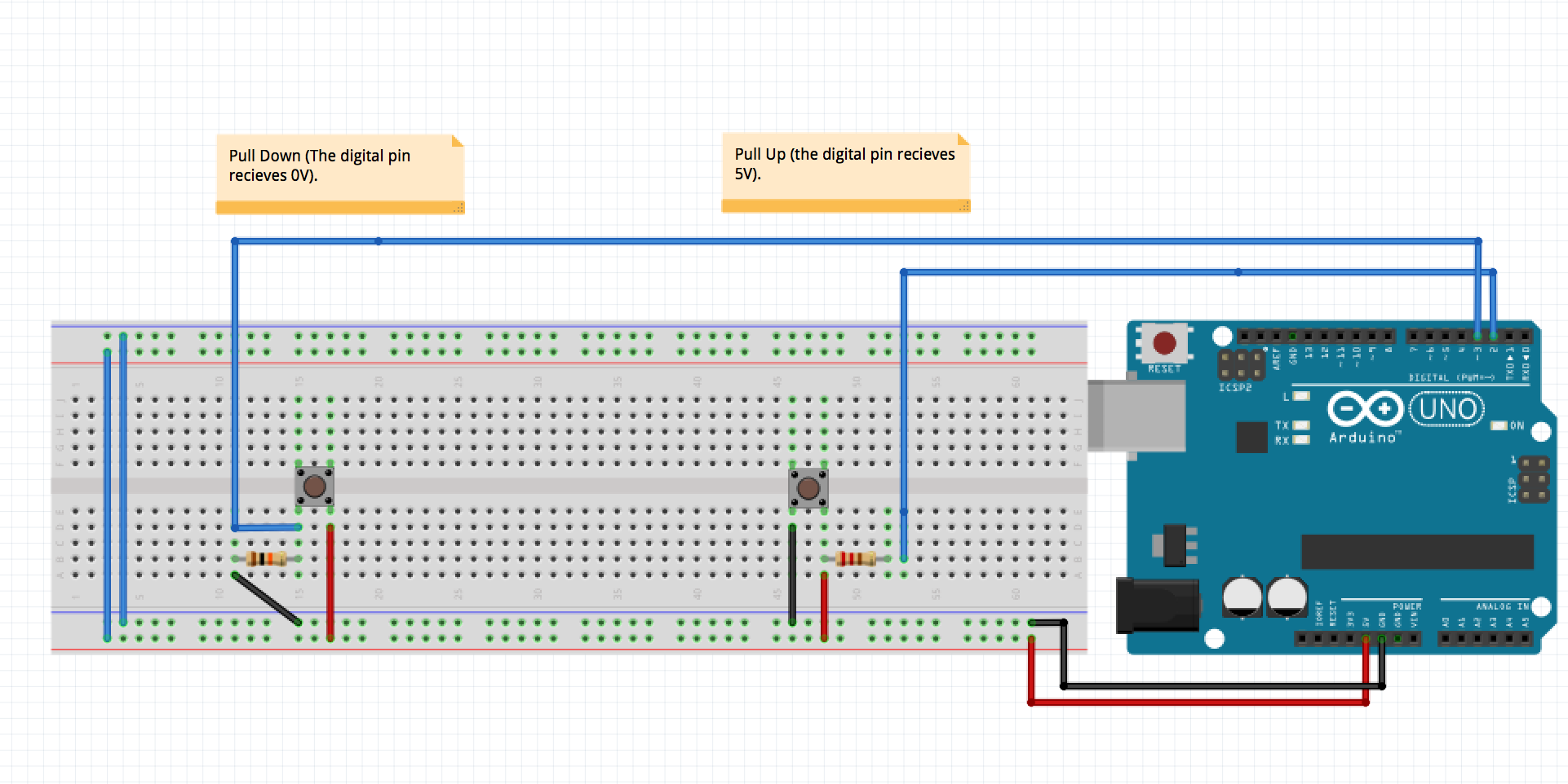
Here is the Fritzing sketch that we made during class.
Here is the Arduino digital button program:
// constants won't change. They're used here to

// set pin numbers:

const int buttonPin = 2; // the number of the pushbutton pin

const int ledPin = 13; // the number of the LED pin
// variables will change:

int buttonState = 0; // variable for reading the pushbutton status
void setup() {

// initialize the LED pin as an output:

pinMode(ledPin, OUTPUT);

// initialize the pushbutton pin as an input:

pinMode(buttonPin, INPUT);

}
void loop(){

// read the state of the pushbutton value:

buttonState = digitalRead(buttonPin);
// check if the pushbutton is pressed.

// if it is, the buttonState is HIGH:

if (buttonState == HIGH) {

// turn LED on:

digitalWrite(ledPin, HIGH);

}

else {

// turn LED off:

digitalWrite(ledPin, LOW);

}

}