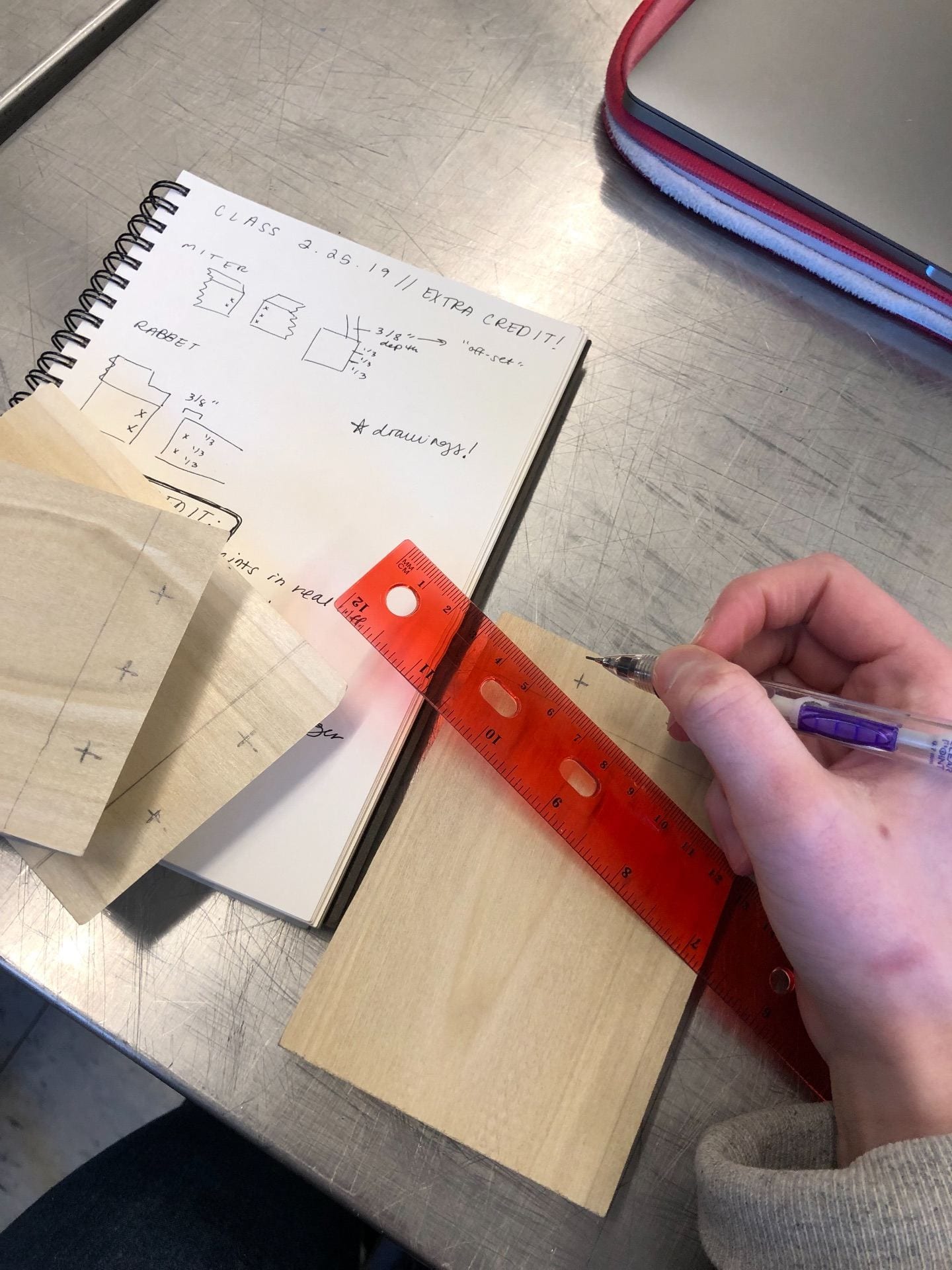
Before building the 5 wood joints, I created drawings for each of the joints, including a front on view, birdseye view, and a side perspective with measurements in the metric system. The drawings really aided my understanding both in how the joints work and how to best construct them, especially when it came to using woodshop tools and hand tools.
The miter joint
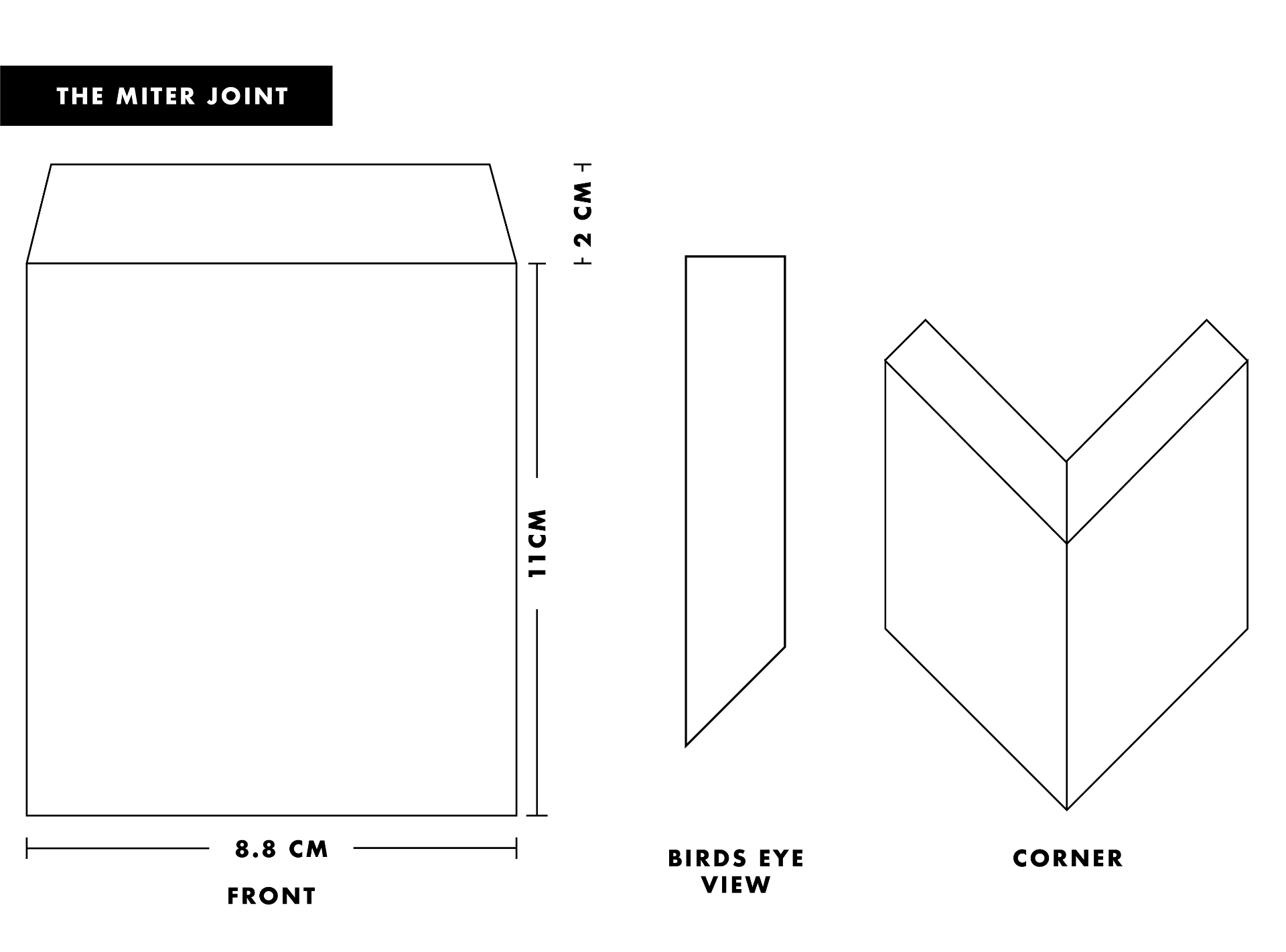
For the miter joint, I began by mapping out a 45-degree guide on the edge of the wood for each piece. Essentially, I drew a perfect cube on the width of the block of the wood and then cut it diagonally to make a triangle, to then serve as a guide for cutting.
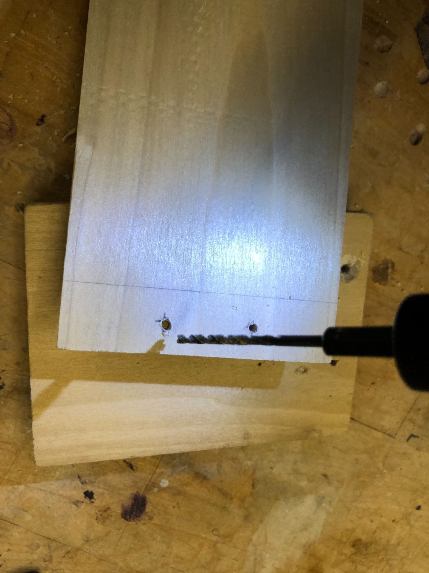

For the actual cut, I used the band saw to cut across and then used the sander for a smooth finish with a true 45-degree angle. To join the two pieces together, I first measured even 1/3’s down on one side of the wood and marking a spot for each third at 3/8″ thick (or half the width of the wood block). On the other piece of wood, I repeated the same process, except I measured 1/4″ down, thus making 3 marks on one piece and two on the other. After marking the center of the mark with an ice pick, I then used a thin drill bit and drilled holes through each of the x’s.
For nailing the wood together, I first clamped the pieces together and lightly tapped each of the nails into the other side, about half way, for each nail before fully hammering them in. I then set the nails further into the wood and covered up the holes with sawdust.
//////////////////////////////////////////////////////////////////////////////////////////////////////////////
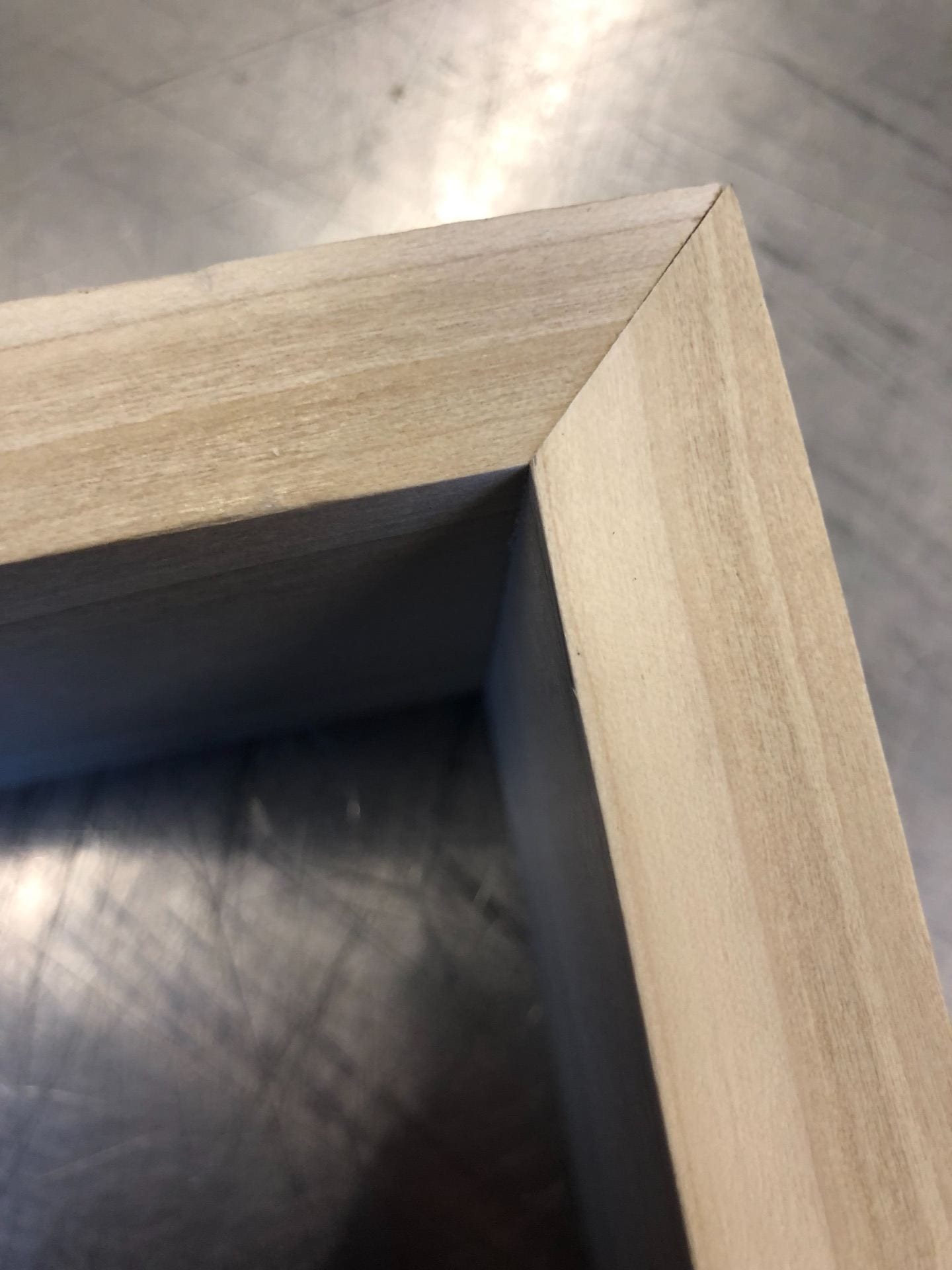
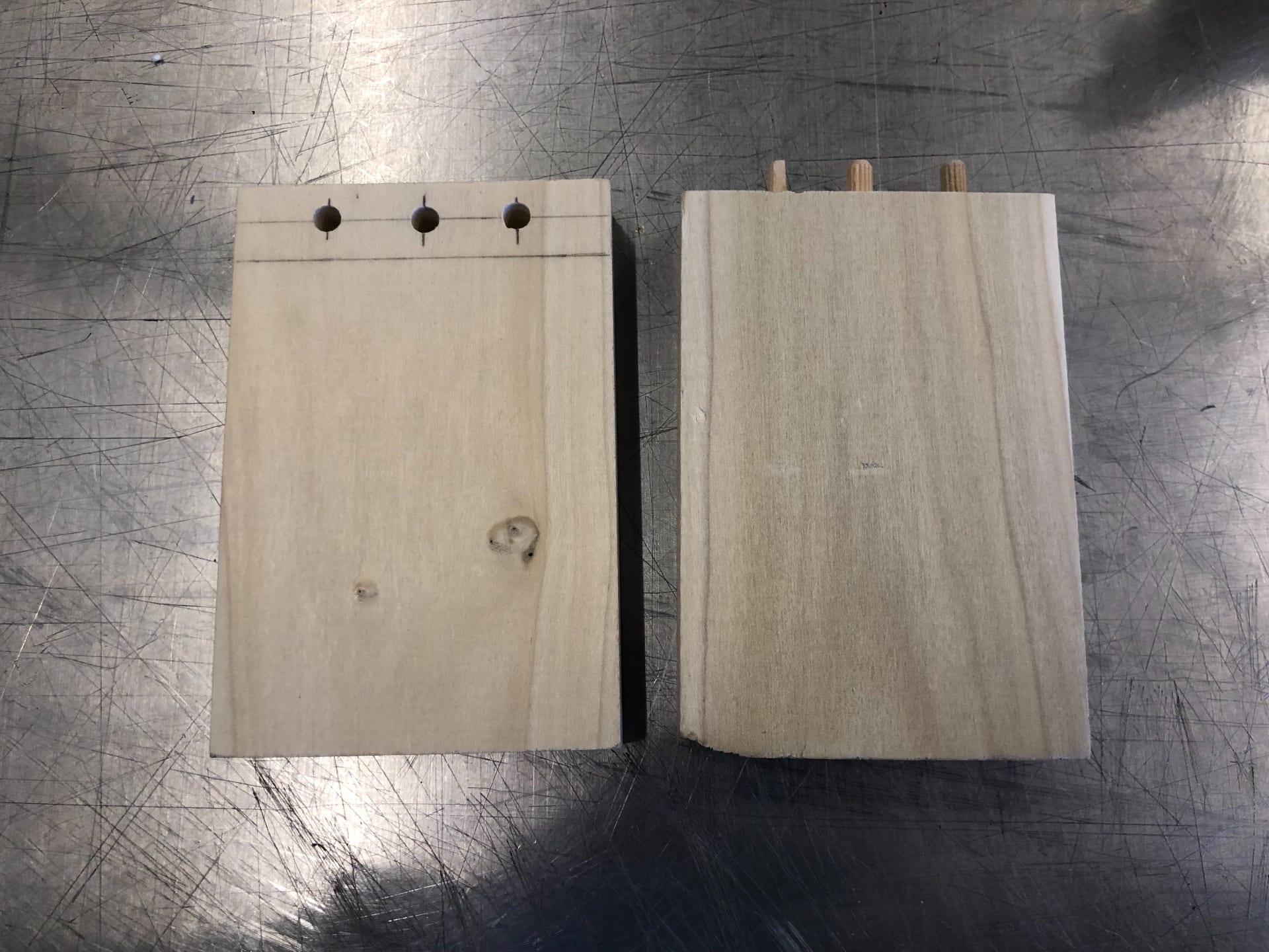
The butt-dowel joint
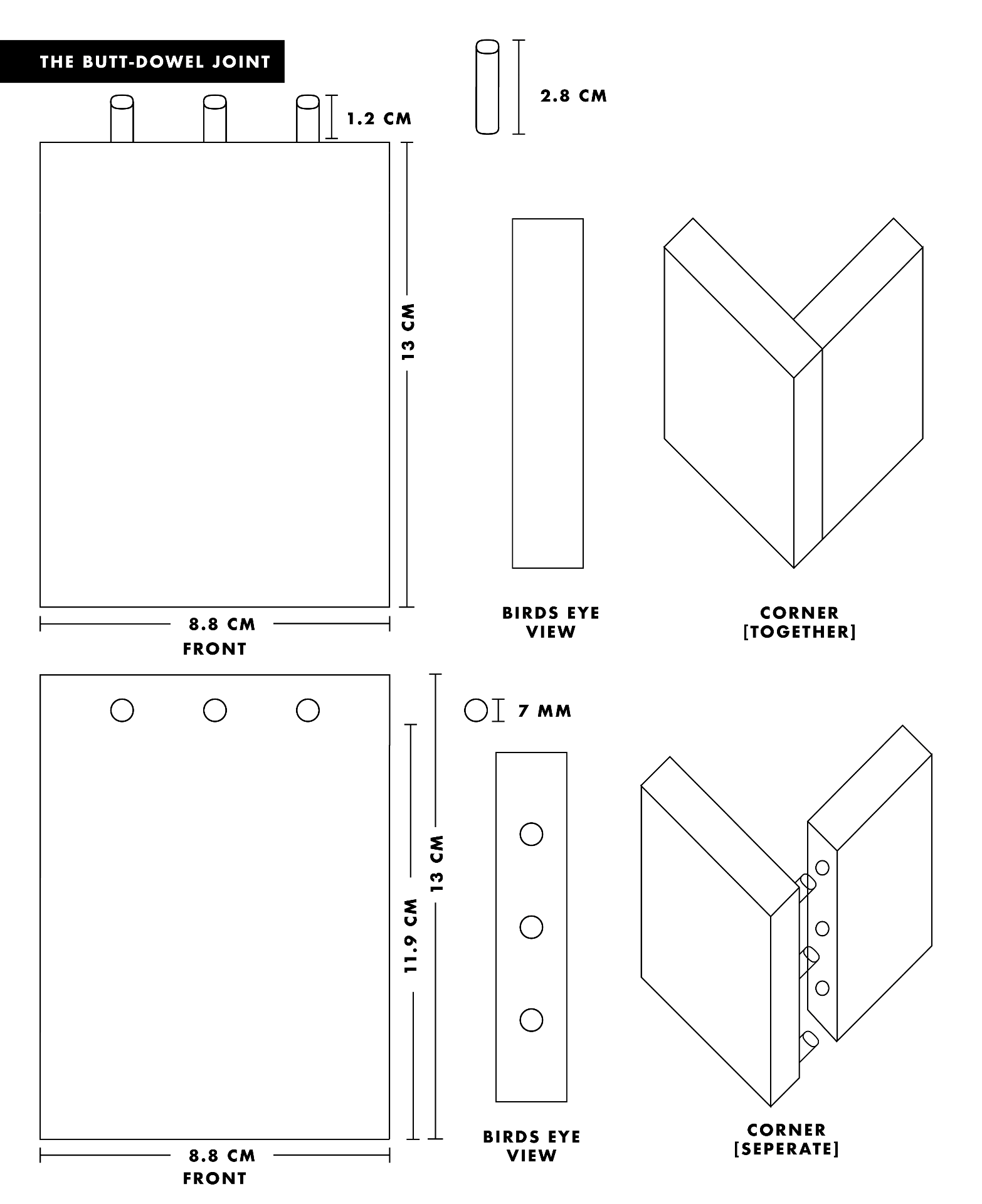
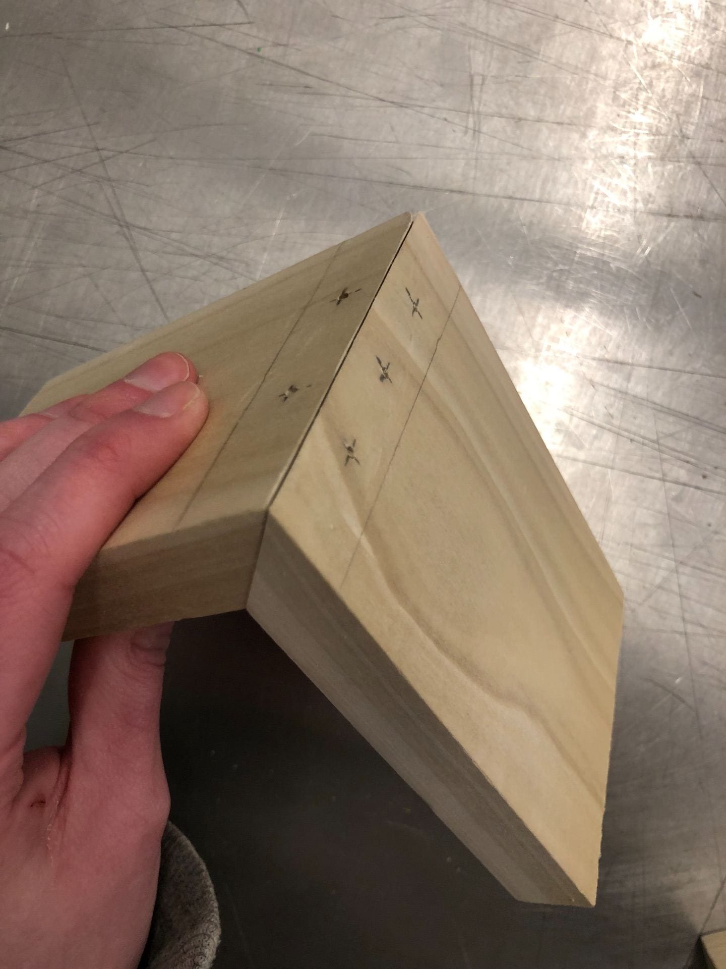
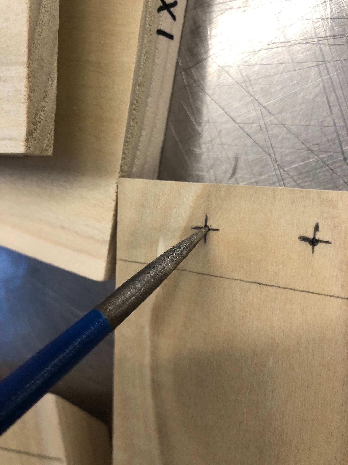
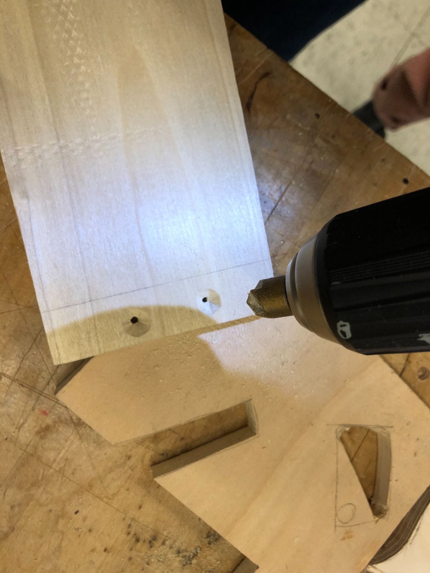
Contrary to my initial thoughts, my drawings clarified that for actually constructing this joint, I should mark intersections of where I want the drill press to be centered in, rather than the holes themselves. This was a crucial step in setting up and anchoring the drill press to accurately mark my wood.
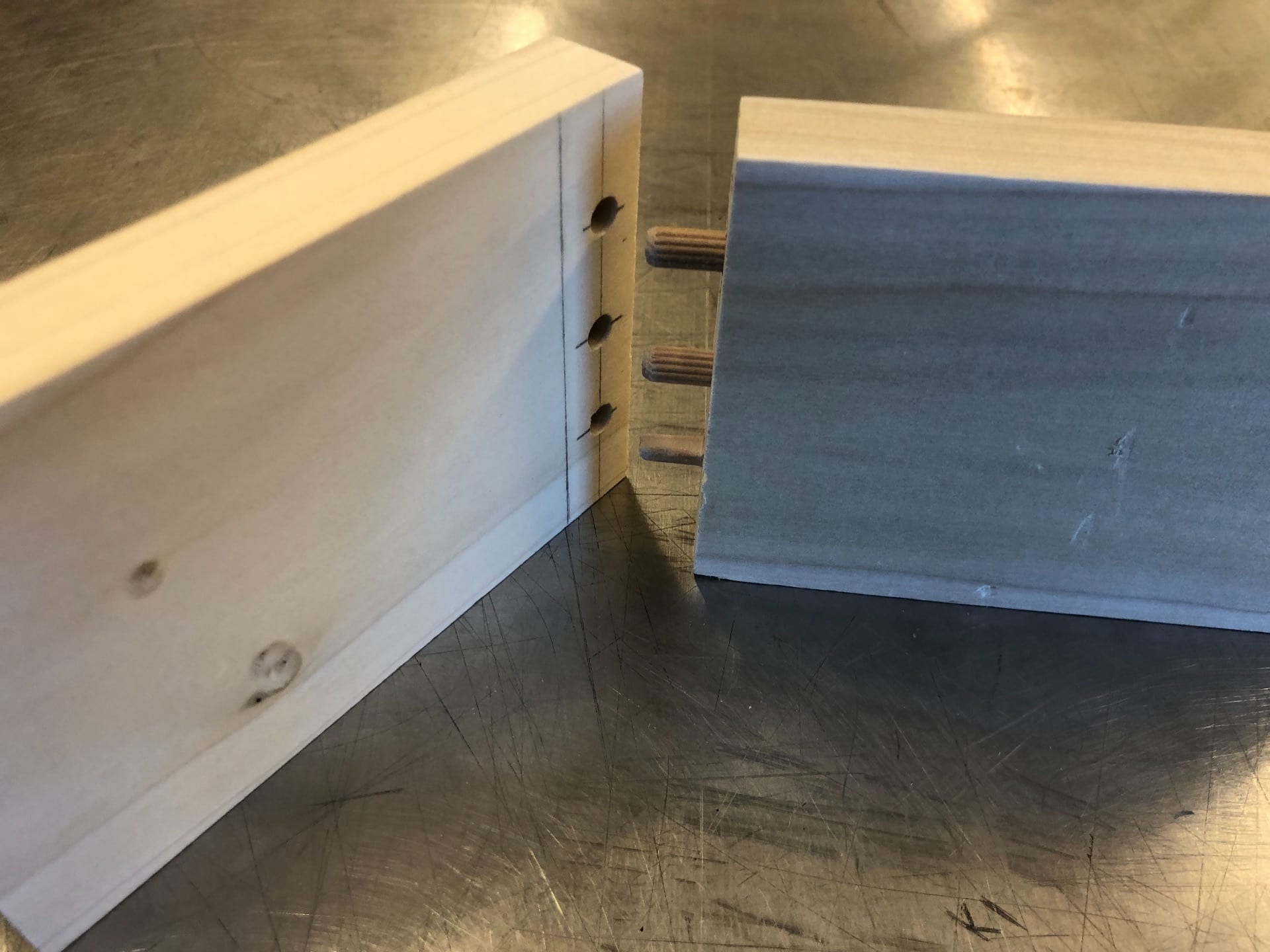
For the cut, I used my markings and drilled ½” down per each hole created. In order to have an accurate depth, we marked ½” on the drill bit with blue tape so we didn’t have to deal with guessing or uneven depths.
After drilling one side, we used 3 small drill bits and lined up the wood accurately to then press and indent where to drill the following three holes. Following the same process as before, after the three holes were drilled, I inserted three 1” dowels to join the wood together.
//////////////////////////////////////////////////////////////////////////////////////////////////////////////
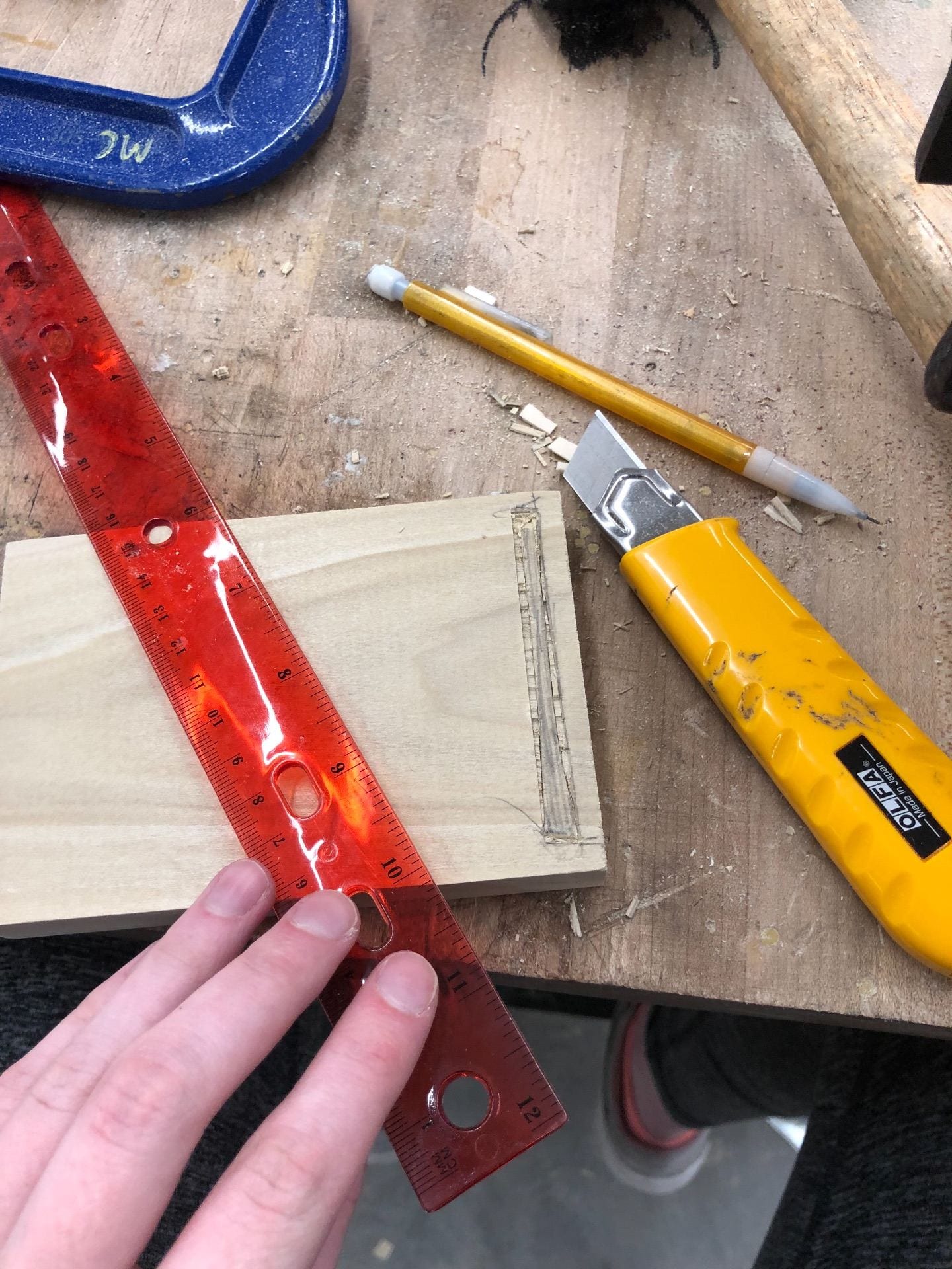
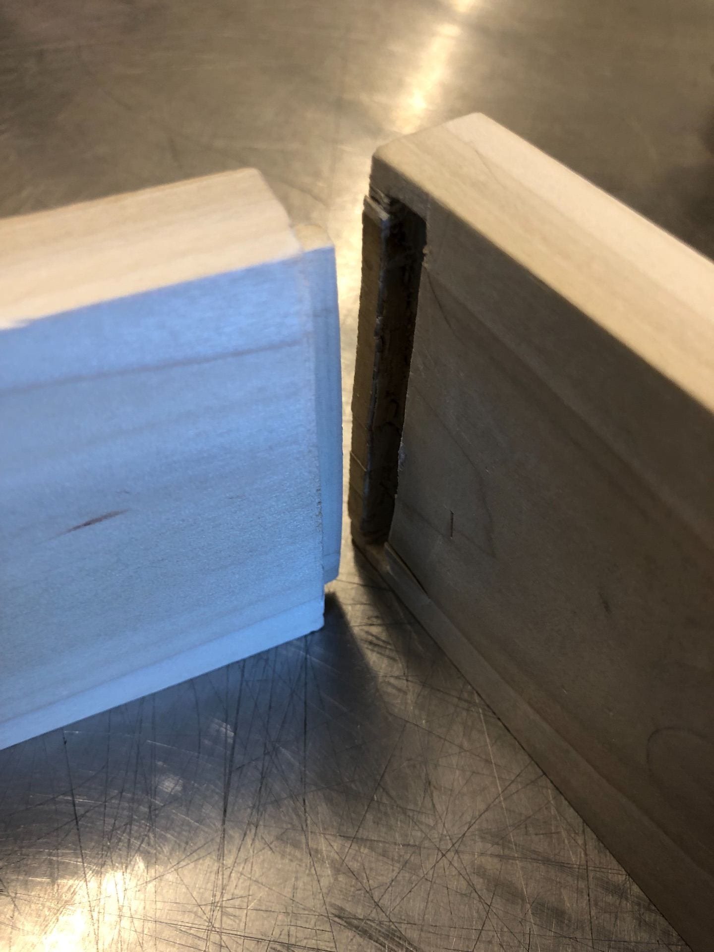
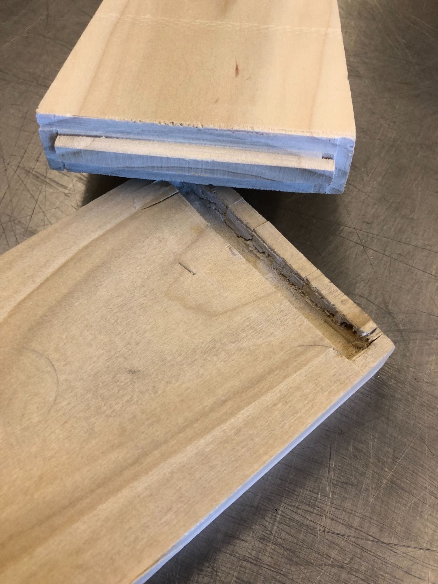
The rabbet joint
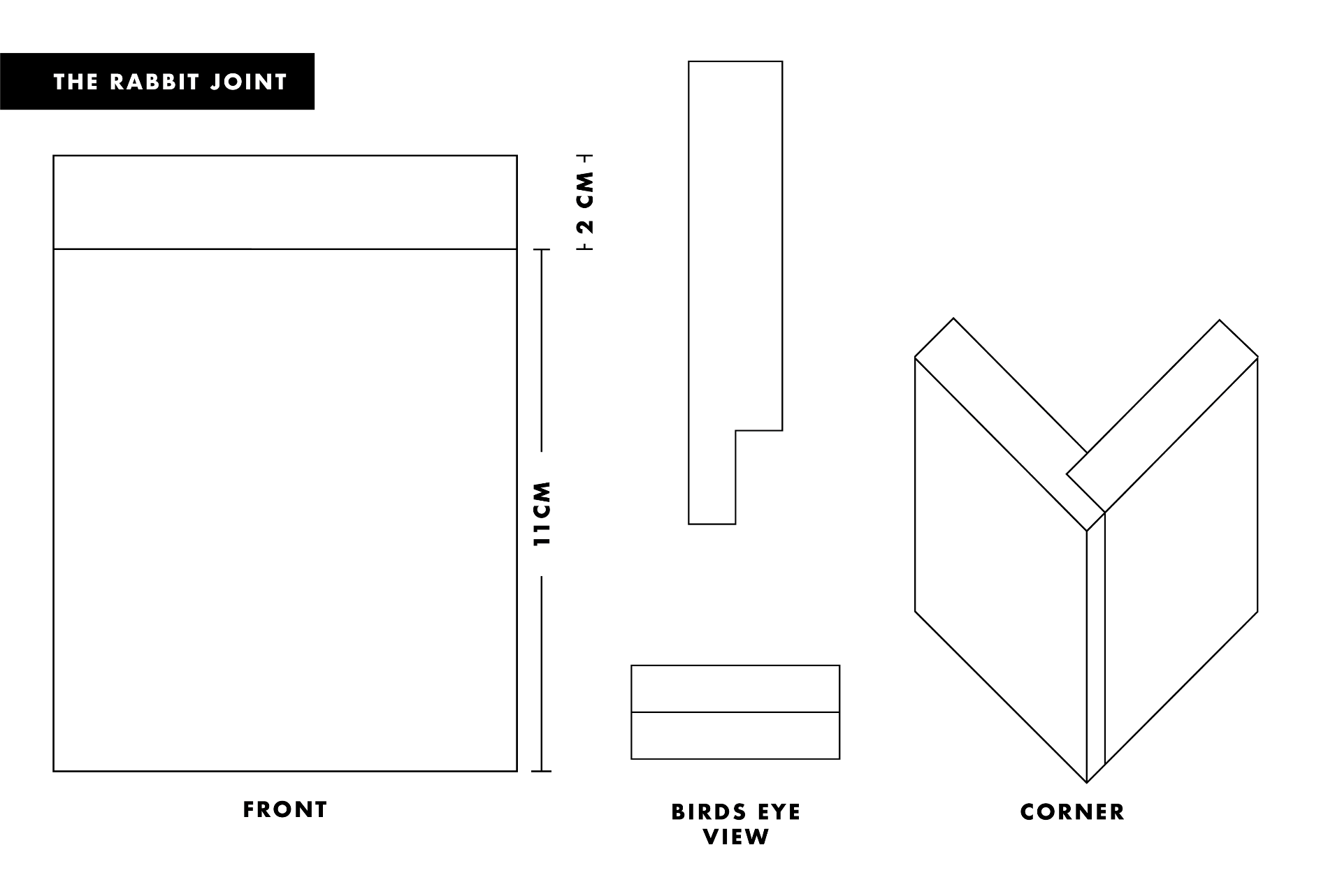
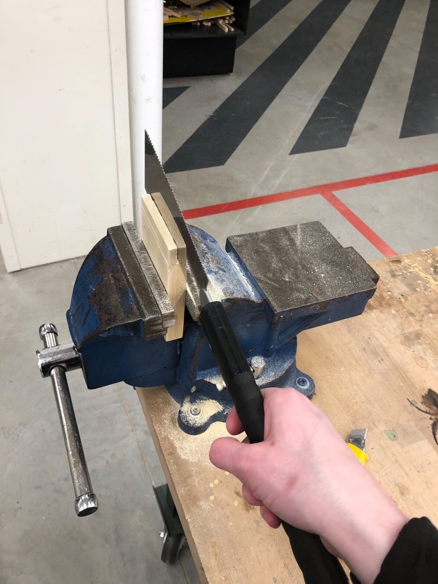
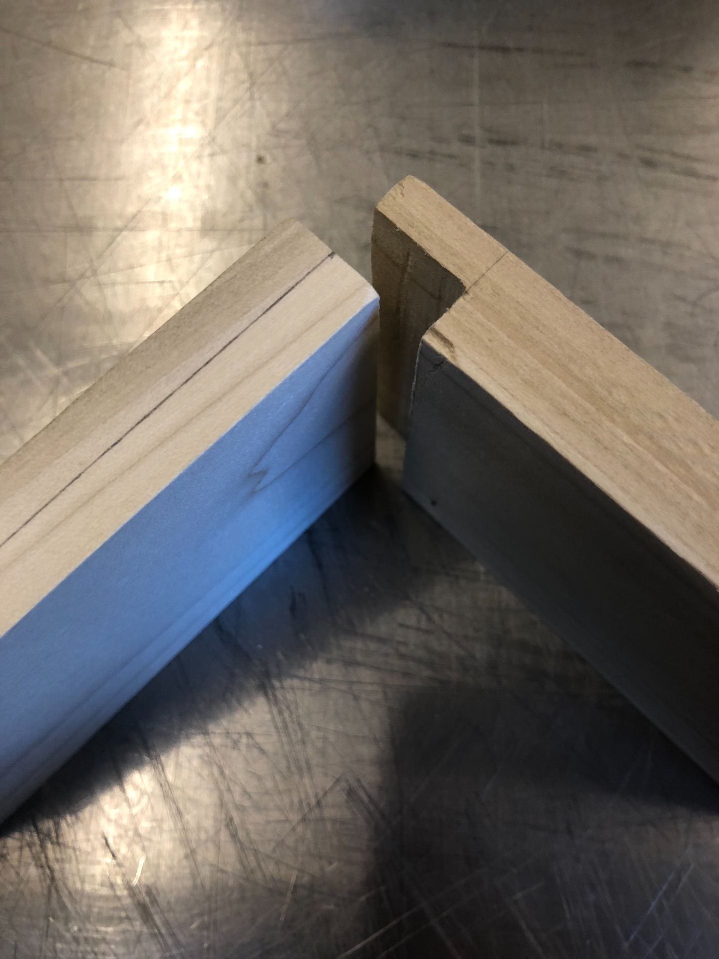
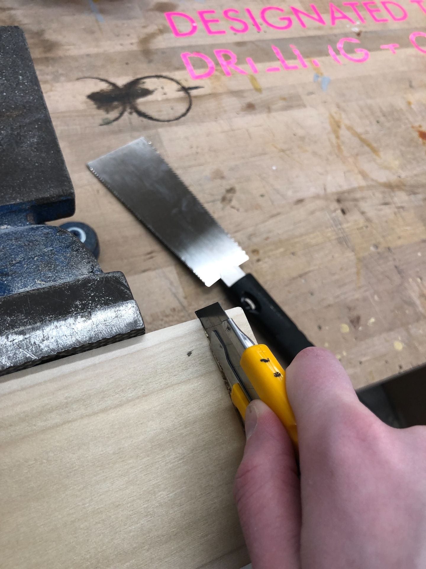
For the rabbit joint, the key was accurately measuring and scoring the line to saw done before jumping straight to the Japanese saw.
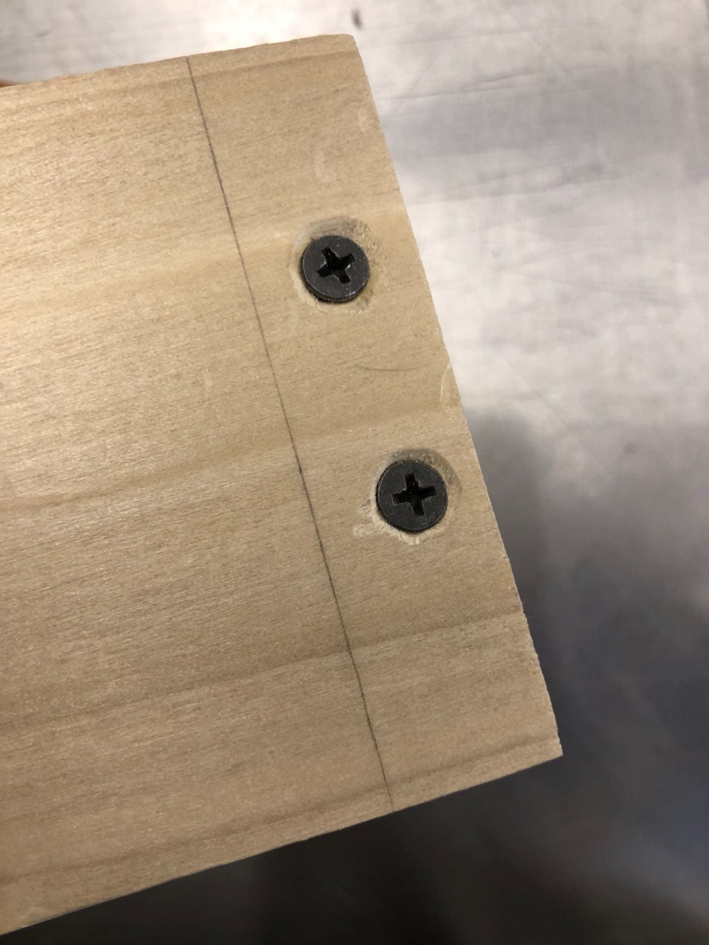
Once I scored the cuts to make, I first cut the length of the wood block, then I turned it on its side and cut downwards. The key was using a ½” file to smoothen out my cut job so the pieces would fit together. To fasten the joint, I marked even 1/3’s down one side of the wood, 1/2 the width in. I then used the ice pick to mark the center of these points and used a drill bit and drilled through, with a larger bit. I then used an additional drill bit, wider in diameter, to create a cradle to hold the head of the screw so that the wood surface would flush and not stick out. Had this been a professional/joint for a project, wood putty would have then been used overtop of the hole to make the screw head invisible.
//////////////////////////////////////////////////////////////////////////////////////////////////////////////
The finger joint (aka box joint)
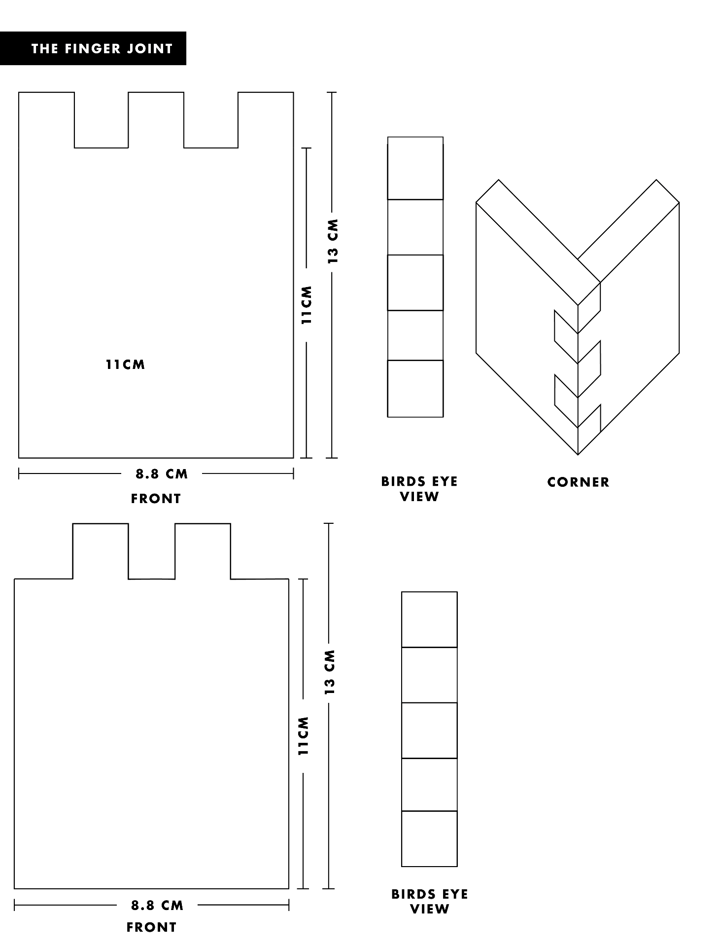
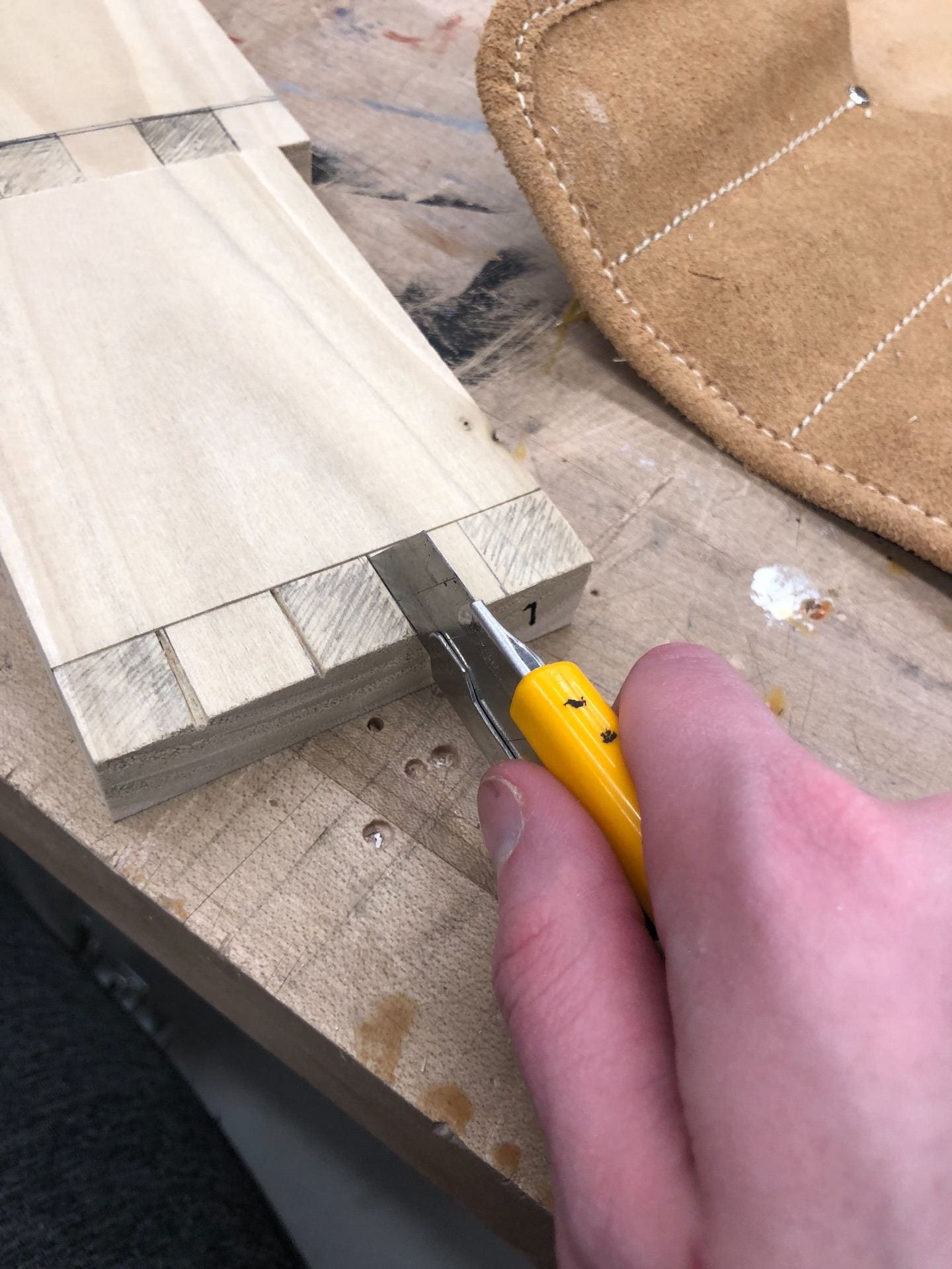
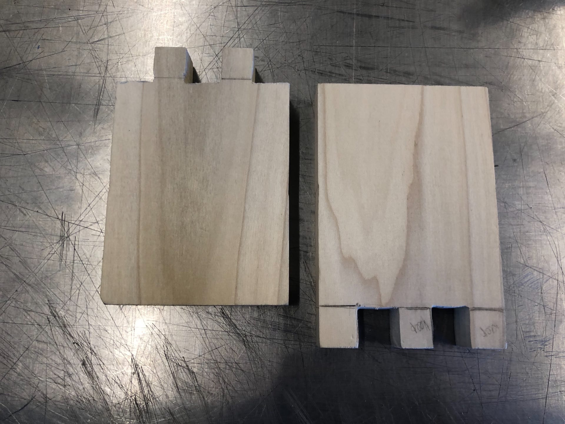
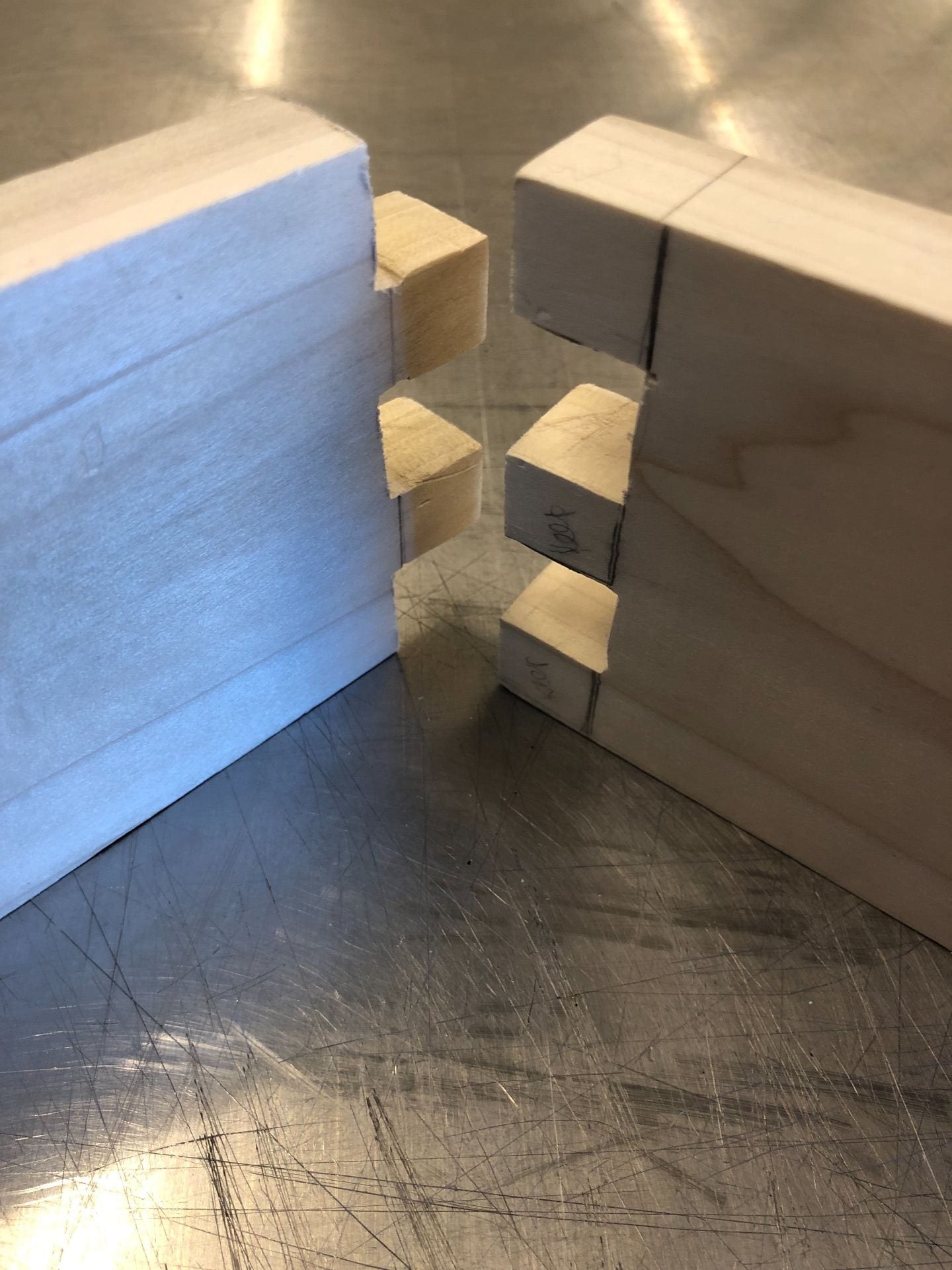
Similar to the drill press, for the finger joint, one should accurately measure one wood block and then make cuts based off the first woodcut, rather than cutting both from drawings. After scoring and cutting one side’s fingers, I traced and then cut the subsequent fingers on the other wood block using the Japanese hand saw. I then filed and smoothed all the edges until they fit together.
//////////////////////////////////////////////////////////////////////////////////////////////////////////////
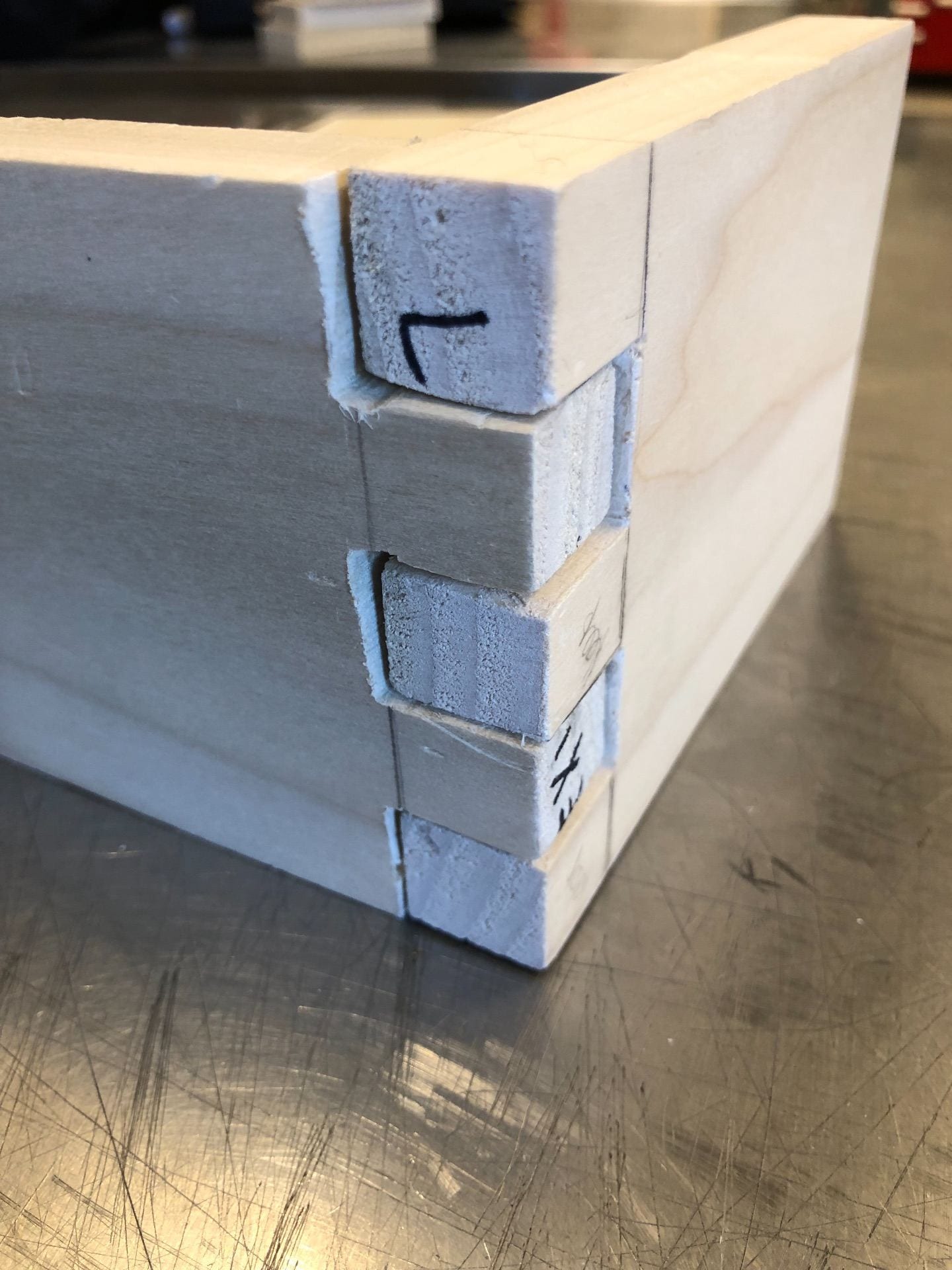
The mortise & tenon joint
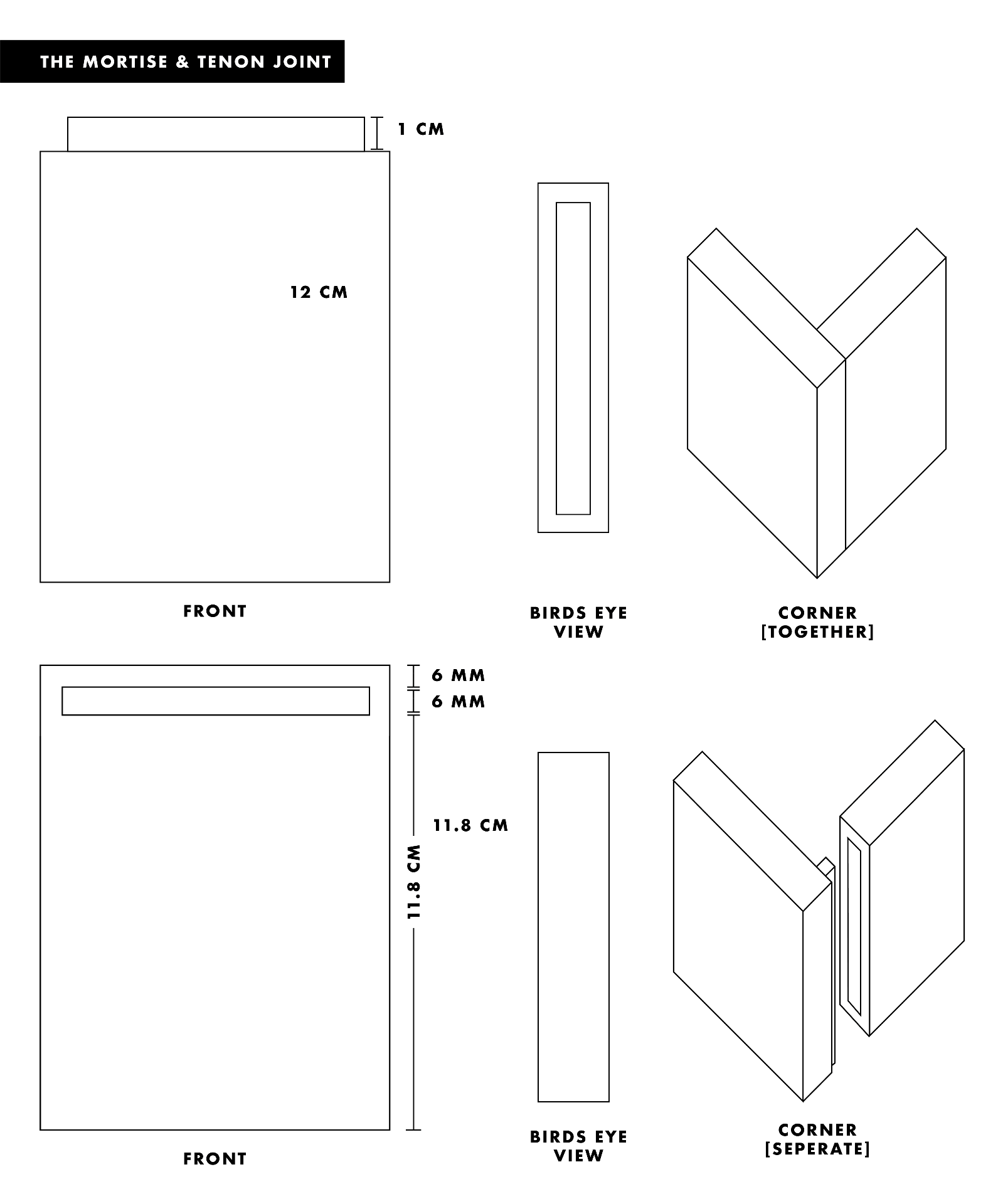
After measuring and scoring the tenon, I used the Japanese hand saw to cut two vertical and two horizontal lines, outlining the face of the tenon. I then sawed inward and followed with the file to smooth the face of the tenon. I think lined up then tenon with the other wood block and drew an outline of then tenon to follow. For the mortise, I scored and then carefully chiseled away the interior until the tenon fit, making sure to file the bottom for a smooth, secure fit.
//////////////////////////////////////////////////////////////////////////////////////////////////////////////
extra credit: real-life joint examples
For extra credit for this assignment, I researched and found real-life examples of all the joints we practiced for this exercise in the real world, specifically in furniture designs. This exercise made me really aware of both how everyday objects I use are built, but more so how I can implement this design into my work to create 3D structures.
mortise and tenon:

image source: Kerf Design
finger joint:

image source: LBR
rabbet joint:
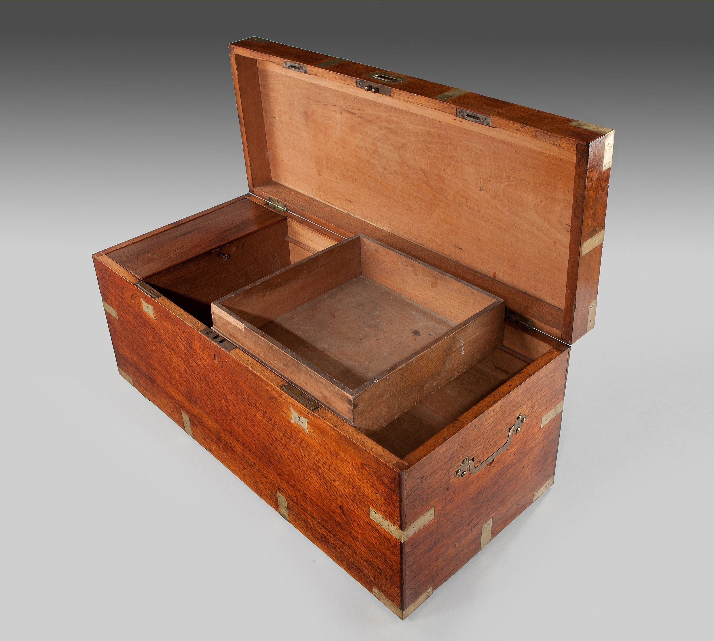
image source: David Silliman
butt-dowel joint:

image source: Fine Woodworking
miter joint:

image source: Woodland Creek Furniture
//////////////////////////////////////////////////////////////////////////////////////////////////////////////
extra credit: finger joint box
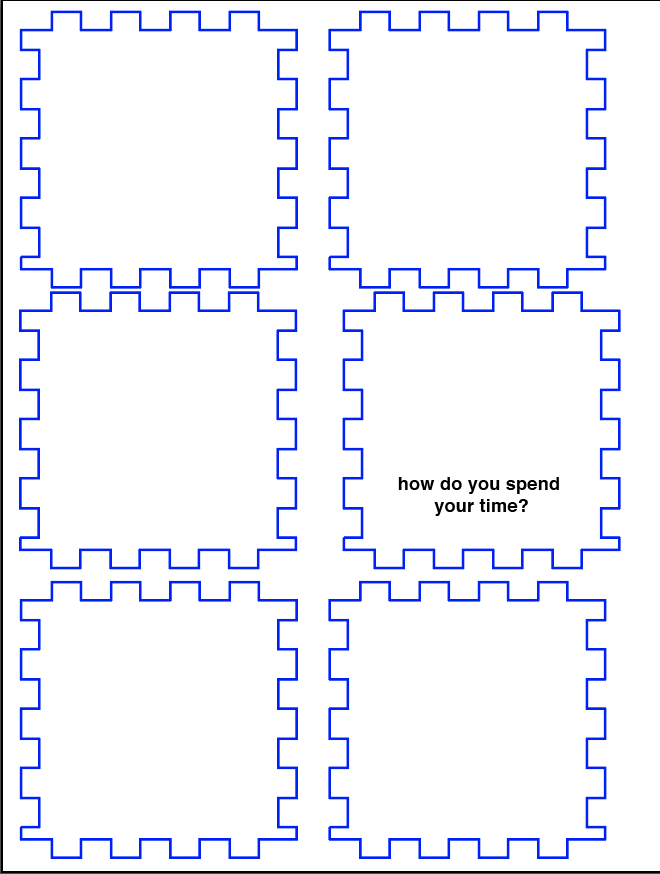
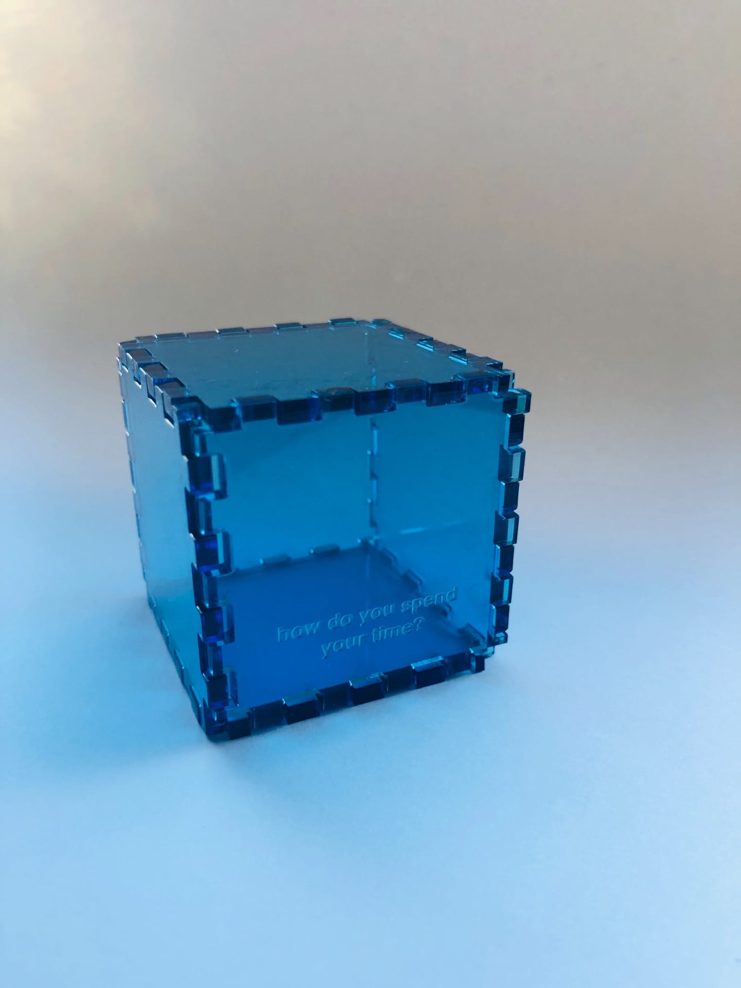
For additional extra credit, I constructed a box to hold game chips for a toy I made in another class. For the box, I created a series of finger joints 1/8″ in depth, the material’s thickness, on clear acrylic. The box was constructed of six identical cube pieces, thus a master copy was created. I made sure to evenly space a series of grids, with one side having 4 fingers, the other having five. I used several images for reference, including this one:

(source: Core Electronics AU )
Below is the drawing I came up with for the box pieces. After measuring and fitting together each of the sides, I laser cut the joints and came up with this box! All in all, I would say that this exercise served as a great tool in helping myself understand both how the finger joint works and how crucial it can be in aiding simple design problems without the use of harmful (and often toxic) glue adhesives or glues.