Studio/Lab Final Presentation – Make a Face!

Final Presentation Slides: makeAFacePresentation

Video: https://vimeo.com/127794759


Notes on Reflection

Unlike most of my other projects that I could quickly settle down for one solid idea, this project went through several iterations until I reached the final idea – a witty and playful interaction/game between human vision and computer vision. Through the user testing, especially from the advice of my game design colleagues, the most valuable lesson that I learnt was the step-by-step instruction for the users to adapt to the rules and speed of the game. I tried using icons and visuals, instead of heavy texts, to more intuitively direct the players into the game. However, to understand the meaning of each icon still required more tolerance of the game in the beginning. Aside from the structure of the game, I found one ideology in Rory’s notes that could push the potential of the project further. Rory suggested that many networks, especially social networks, intentionally yet unconsciously steered us to certain emotions or encouraged us to participate in some activities. For instance, social networks encourage us to be engaged with friends, while shopping websites sell the products as well as the pleasant mood of buying things. Therefore, this project could become a critical object on exploring the unconsciously control of guidance of our emotion and activities, which could be as equally threatening as public surveillance.
[Lab: Environment] LED Matrix 8×8

brightness

IMG_2637

IMG_2638

IMG_2642


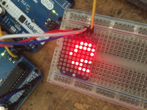
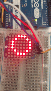
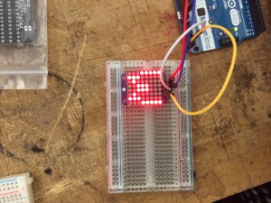
In class, we soldered the 8×8 LED matrix onto its driver board, both from Adafruit. We downloaded the two libraries from Adafruit and ran the examples in Arduino IDE. In the code, the LED matrix is divided by lines, and for each line there is 0 for off and 1 for on. Therefore, we can easily create our own patterns. What is even more helpful is the functions already written in the library, which enabling us to directly type letters or common shapes like circles and rectangles. The most interesting part for me is probably the brightness function that I can set from 0 to 16. So I put it inside a for-loop with a slight delay in the end. Then the LED matrix starts to breathe/blink (click the first picture to see gif).


Here is the code for the blinking circle:

#include <Wire.h>
#include “Adafruit_LEDBackpack.h”
#include “Adafruit_GFX.h”

Adafruit_8x8matrix matrix = Adafruit_8x8matrix();

void setup() {
Serial.begin(9600);
Serial.println(“8×8 LED Matrix Bitmaps”);

matrix.begin(0x70);
}

static const uint8_t PROGMEM
w_bmp[] =
{
B10000001,
B10000001,
B10000001,
B10011001,
B10011001,
B01011010,
B01100110,
B01000010,
};

void loop() {
// matrix.clear();
// matrix.drawBitmap(0,0, w_bmp, 8, 8, LED_ON);
// matrix.writeDisplay();
// delay(500);
//
// matrix.setTextSize(1);
// matrix.setTextWrap(false); // we dont want text to wrap so it scrolls nicely
// matrix.setTextColor(LED_ON);
// for (int8_t x=0; x>=-36; x–) {
// matrix.clear();
// matrix.setCursor(x,0);
// matrix.print(“Yumeng”);
// matrix.print(“is”);
// matrix.print(“genius”);
// matrix.writeDisplay();
// delay(100);
// }

matrix.clear();
// matrix.drawCircle(random(0,7),random(0,7), random(1,5), LED_ON);
matrix.drawCircle(3,3, 3, LED_ON);
matrix.writeDisplay(); // write the changes we just made to the display
for (int i = 0; i<=16; i++){
matrix.setBrightness(i);
delay(45);
}

delay(10);
}


[Lab: Environment] Labduino

breather

(Click on the picture to see the gif.)

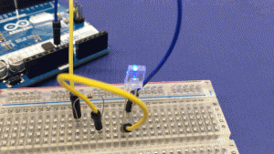
The LED breather example from class uses a PWM pin to simulate an analog output to dim the LED. AnalogWrite actually still uses digital output, but controls the percentage of the time of on or off to make the pseudo analog output. (analog output)

I found a reference to make the real analog output buy connecting a capacitor to filter the voltage during on or off, in order to average the voltage. http://arduino-info.wikispaces.com/Analog-Output

IMG_2551

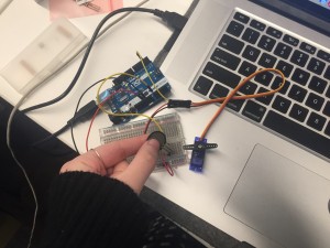
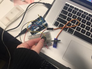
Force resistive sensor controlling a servo motor (analog input – digital output)

photo 3-1

Sound impact sensor controlling a stepper motor (digital input? – analog output)

Meanwhile, the serial monitor prints out the input as 1 or 0. (Serial output)

Screen Shot 2015-02-09 at 12.40.53 PM

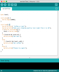
A serial in sketch to help the use choose between coffee and tea. (Serial input)


[Lab: Environment] LabDuino Work in Progress


For the first part of the LabDuino, we connected a photocell, as the analog input, and an LED, as the digital output, and made the LED dim according to how much light the photocell was exposed to. (Unfortunately I forgot to take a picture of this part.)

For the second part, I connected a force resistive sensor to a servo. Same problem appeared as before: the servo shakes all the time, due to the fast fluctuation of the analog input. After class, Michael helped me to solve this problem by sending the average number of 150 input values to the servo, so that it will move more smoothly. I understood the logic of this part, but we did not succeed yet with the new modified code. Hope we can fix it in next class.

IMG_2551


For the next, I can’t wait to use the parts that I have not used before, such as joysticks, accelerometers/gyros, LED matrixes, etc.

[Lab: Environment] Posts on Arduino Forum

Team: Innocent Arduino Beginners

Team members: Kim, Sean, Shubs, Yumeng


The following links are the two introductory Arduino questions that we posted on the forum. People are nice. We’ve got answers in an hour!

http://forum.arduino.cc/index.php?topic=296919.0

http://forum.arduino.cc/index.php?topic=296930.0


In addition, all of my posts for Core Lab:Environment will start with [Lab: Environment] and they can be found under Topics: Core Lab: Environment at the bottom of the blog.