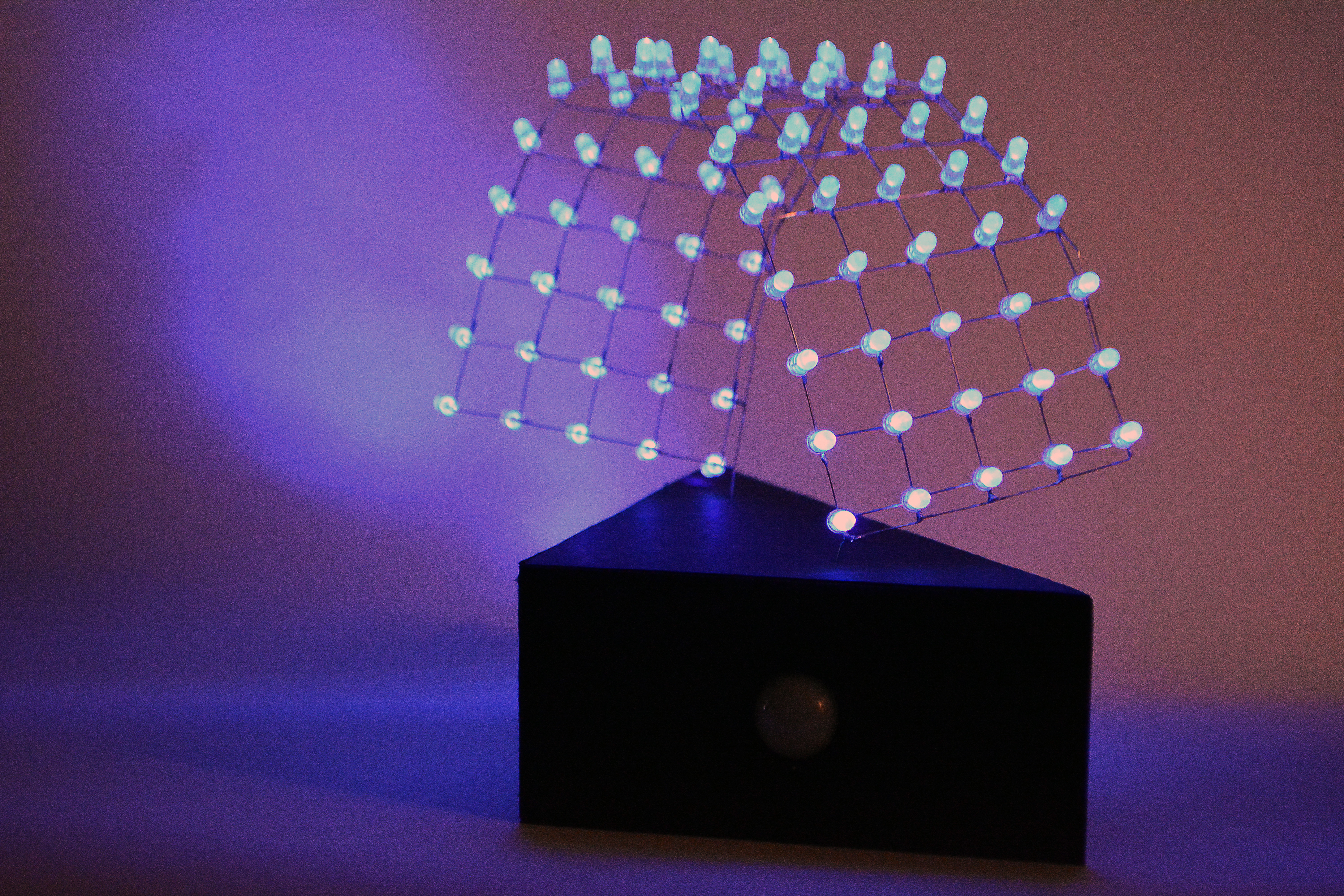
For this project my main idea was to create 3-dimensional sculpture from LED’s.
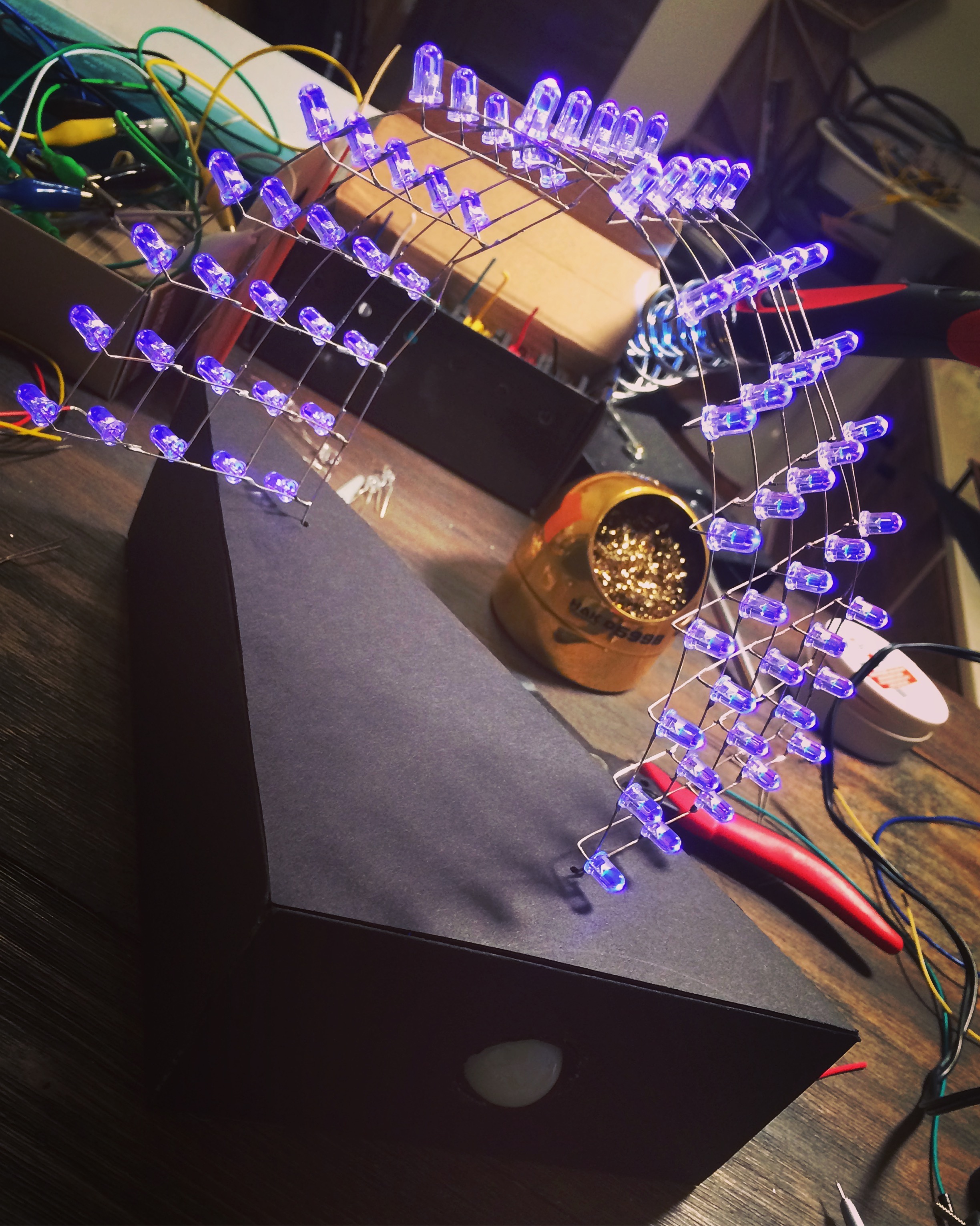
First I looked at LED screens, but didn’t like that they are flat, LED cube grabbed my attention, but I wanted something more organic. I didn’t know how my sculpture would end up looking, but I started by learning how to connect LED’s into grid to create this circuit. I learned that all negative legs bent to right (or left) and soldered in horizontal rows, and positive legs bent to the bottom (or up) and soldered together forming series of vertical rows.


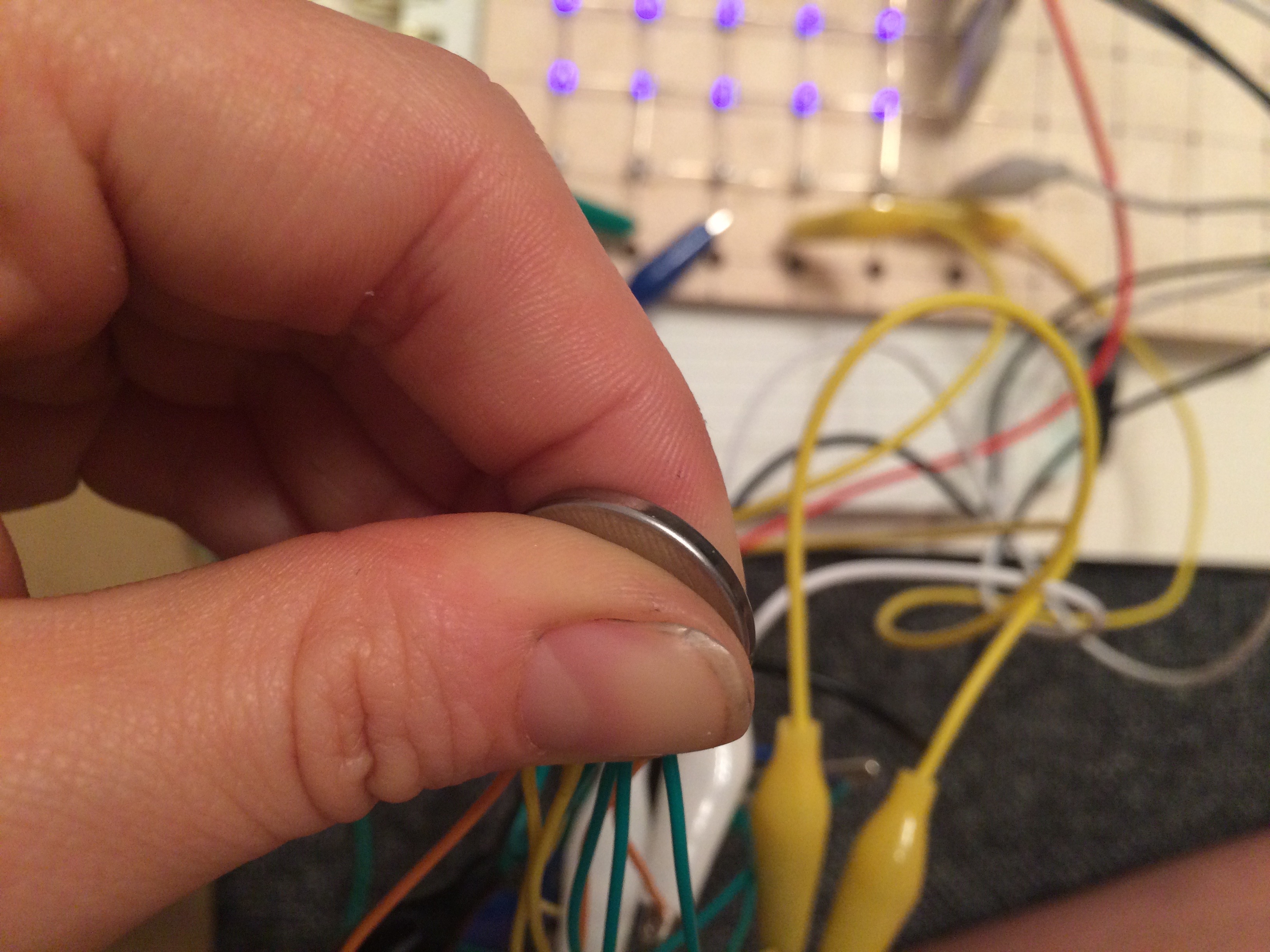

Further I had quite a bit of different explorations within the realm of multiplexing, I tried different circuits and codes. I tried to connect each row to arduino pins, and access LED’s through creating temporary mini circuits. I tried to use a tutorial I found online that was supposed to make letters run through the grid but I couldn’t completely understand the four for loop they were using, so I couldn’t successfully modify it. Also I tried to lazer cut a box for my electronics, but acrylic got caught on fire.


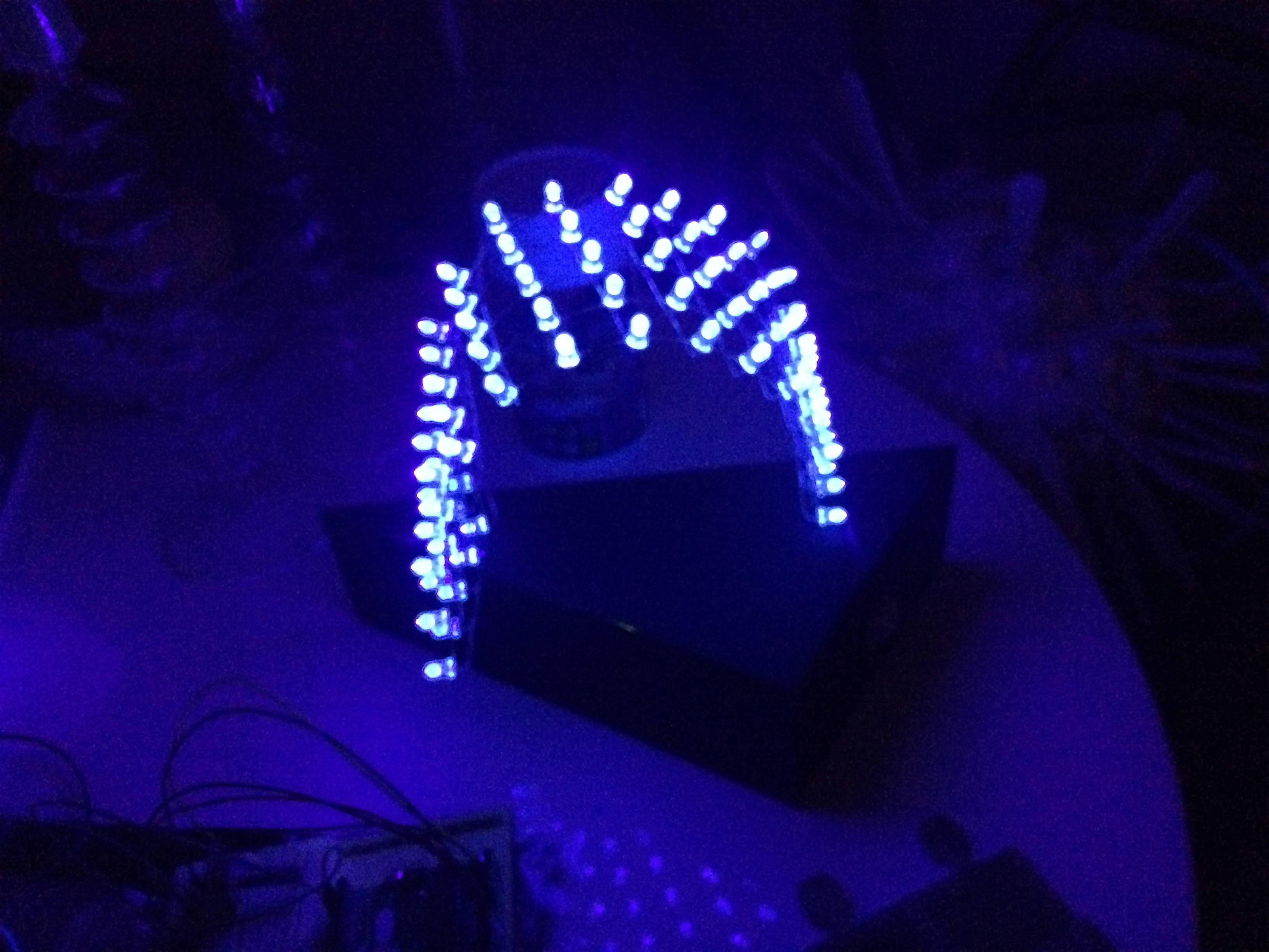
Since time was limited I decided to stop my experiments, and deliver whatever I had at the moment. I extended LED grid, which has now a total of 75 LED’s. I added motion censor, and hid electronics into a triangular shape box I cut from foam-core.


After I completed this sculpture I have an idea now how I can animate rows of LED’s running.
Codes:
1st experiment
/*int Col1 = 13;
int Col2 = 12;
int Col3 = 11;
int Col4 = 10;
int Col5 = 9;
int Row1 = 8;
int Row2 = 7;
int Row3 = 6;
int Row4 = 5;
int Row5 = 4;
void setup() {
pinMode(Col1,OUTPUT);
pinMode(Col2,OUTPUT);
pinMode(Col3,OUTPUT);
pinMode(Col4,OUTPUT);
pinMode(Col5,OUTPUT);
pinMode(Row1,OUTPUT);
pinMode(Row2,OUTPUT);
pinMode(Row3,OUTPUT);
pinMode(Row4,OUTPUT);
pinMode(Row5,OUTPUT);
}
void loop() {
digitalWrite(Col1,HIGH);
digitalWrite(Col2,HIGH);
digitalWrite(Col3,LOW);
digitalWrite(Col4,LOW);
digitalWrite(Col5,LOW);
digitalWrite(Row1,LOW);
digitalWrite(Row2,LOW);
digitalWrite(Row3,HIGH);
digitalWrite(Row4,HIGH);
digitalWrite(Row5,HIGH);
}
*/
// 2-dimensional array of row pin numbers:
const int row[5] = {
8, 7, 6, 5, 4
};
// 2-dimensional array of column pin numbers:
const int col[5] = {
13, 12, 11, 10, 9
};
// 2-dimensional array of pixels:
int pixels[5][5];
// cursor position:
int x = 5;
int y = 5;
void setup() {
// initialize the I/O pins as outputs
// iterate over the pins:
for (int thisPin = 0; thisPin < 5; thisPin++) {
// initialize the output pins:
pinMode(col[thisPin], OUTPUT);
pinMode(row[thisPin], OUTPUT);
// take the col pins (i.e. the cathodes) high to ensure that
// the LEDS are off:
digitalWrite(col[thisPin], HIGH);
}
// initialize the pixel matrix:
for (int x = 0; x < 5; x++) {
for (int y = 0; y < 5; y++) {
pixels[x][y] = HIGH;
}
}
}
void loop() {
// read input:
readSensors();
// draw the screen:
refreshScreen();
}
void readSensors() {
// turn off the last position:
pixels[x][y] = HIGH;
// read the sensors for X and Y values:
x = 4 – map(analogRead(A0), 0, 1023, 0, 4);
y = map(analogRead(A1), 0, 1023, 0, 4);
// set the new pixel position low so that the LED will turn on
// in the next screen refresh:
pixels[x][y] = LOW;
}
void refreshScreen() {
// iterate over the rows (anodes):
for (int thisRow = 0; thisRow < 5; thisRow++) {
// take the row pin (anode) high:
digitalWrite(row[thisRow], HIGH);
// iterate over the cols (cathodes):
for (int thisCol = 0; thisCol < 5; thisCol++) {
// get the state of the current pixel;
int thisPixel = pixels[thisRow][thisCol];
// when the row is HIGH and the col is LOW,
// the LED where they meet turns on:
digitalWrite(col[thisCol], thisPixel);
// turn the pixel off:
if (thisPixel == LOW) {
digitalWrite(col[thisCol], HIGH);
}
}
// take the row pin low to turn off the whole row:
digitalWrite(row[thisRow], LOW);
}
}
2nd experiment
int clock = 9;
int reset = 8;
int x;
int y;
#define space {B00000000,B00000000,B00000000,B00000000,B00000000,B00000000,B00000000,B00000000,B00000000,B00000000}
#define full {B11111,B11111,B11111,B11111,B11111}
#define frame {B00111110,B00100010,B00100010,B00100010,B00111110}
#define smallframe {B00000,B01110,B01010,B01110,B00000}
#define single {B00000, B00000, B00100, B00000, B00000}
const int numPatterns = 16;
byte patterns[numPatterns][10]={space,full,space,frame,space,smallframe,single};
void setup()
{
DDRD= B11111111;
pinMode(clock,OUTPUT);
pinMode(reset,OUTPUT);
digitalWrite(reset,HIGH);
delayMicroseconds(5);
digitalWrite(reset,LOW);
}
void loop()
{
// show(25);
//byte temp = patterns[1];
//digitalWrite(clock,HIGH);
PORTD=B11001;
}
//void show(int loops)
//{
// for(x=0;x<numPatterns-1;x++)
// {
// for (int z=0;z<5;z++)
// {
// for(int t=0;t<loops;t++)
// {
// for(y=0;y<5;y++)
// {
// byte temp = patterns[x][y];
// byte temp_2=patterns[x+1][y];
// PORTD = (temp<<z)+(temp_2>>4-z);
// delayMicroseconds(800);
// PORTD=B00000000;
// digitalWrite(clock,HIGH);
// delayMicroseconds(5);
// digitalWrite(clock,LOW);
// }
// }
// }
// }
//}
3rd final code:
int ledPin = 13; // LED
int inputPin = 2; // input pin (for PIR sensor)
int pirState = LOW;
int val = 0; // variable for reading the pin status
void setup() {
pinMode(ledPin, OUTPUT); // LED as output
pinMode(inputPin, INPUT); // sensor as input
Serial.begin(9600);
}
void loop(){
val = digitalRead(inputPin); // read input
if (val == HIGH) { // check if the input is HIGH
digitalWrite(ledPin, HIGH); // turn LED ON
if (pirState == LOW) {
// we have just turned on
Serial.println(“Motion detected!”);
// print on the output change
pirState = HIGH;
}
} else {
digitalWrite(ledPin, LOW); // turn LED OFF
if (pirState == HIGH){
// we have just turned of
Serial.println(“Motion ended!”);
// print on the output change
pirState = LOW;
}
}
}


