


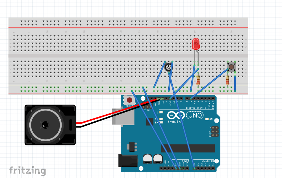
In this fritzing sketch I have connected various inputs and outputs:
input: button [digital] > jumper to pin 6, resistor to ground, jumper to positive
output: LED light [digital] jumper to pin 11, resistor to ground, jumper to positive
input: potentiometer [analog] jumper to a0, jumpers to ground and positive
output: speaker [analog] jumper to pin 13, jumper to ground
So on the breadboard the LED lights up when the button is pressed, and the speaker sings as the pot is turned. As for serial connections, there is a message being spit out by the code [output] and the [input] is the changing numbers coming in from the potentiometer and being listed in the serial monitor. More serial input could be achieved by connecting a photosensor, which can be read by the serial port and output data in numbers.