[Lab: Environment] LED Matrix 8×8
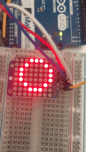
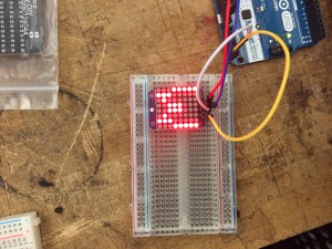
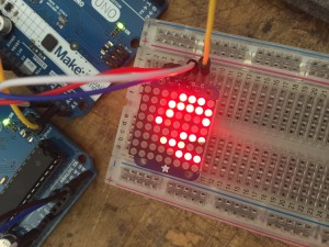
In class, we soldered the 8×8 LED matrix onto its driver board, both from Adafruit. We downloaded the two libraries from Adafruit and ran the examples in Arduino IDE. In the code, the LED matrix is divided by lines, and for each line there is 0 for off and 1 for on. Therefore, we can easily create our own patterns. What is even more helpful is the functions already written in the library, which enabling us to directly type letters or common shapes like circles and rectangles. The most interesting part for me is probably the brightness function that I can set from 0 to 16. So I put it inside a for-loop with a slight delay in the end. Then the LED matrix starts to breathe/blink (click the first picture to see gif).
Here is the code for the blinking circle:
#include <Wire.h>
#include “Adafruit_LEDBackpack.h”
#include “Adafruit_GFX.h”
Adafruit_8x8matrix matrix = Adafruit_8x8matrix();
void setup() {
Serial.begin(9600);
Serial.println(“8×8 LED Matrix Bitmaps”);
matrix.begin(0x70);
}
static const uint8_t PROGMEM
w_bmp[] =
{
B10000001,
B10000001,
B10000001,
B10011001,
B10011001,
B01011010,
B01100110,
B01000010,
};
void loop() {
// matrix.clear();
// matrix.drawBitmap(0,0, w_bmp, 8, 8, LED_ON);
// matrix.writeDisplay();
// delay(500);
//
// matrix.setTextSize(1);
// matrix.setTextWrap(false); // we dont want text to wrap so it scrolls nicely
// matrix.setTextColor(LED_ON);
// for (int8_t x=0; x>=-36; x–) {
// matrix.clear();
// matrix.setCursor(x,0);
// matrix.print(“Yumeng”);
// matrix.print(“is”);
// matrix.print(“genius”);
// matrix.writeDisplay();
// delay(100);
// }
matrix.clear();
// matrix.drawCircle(random(0,7),random(0,7), random(1,5), LED_ON);
matrix.drawCircle(3,3, 3, LED_ON);
matrix.writeDisplay(); // write the changes we just made to the display
for (int i = 0; i<=16; i++){
matrix.setBrightness(i);
delay(45);
}
delay(10);
}


Leave a Reply