This website offers a great multi-step tutorial on interfacing with an arduino via HTML.
Month: September 2014
Another tutorial for using the arduino ethernet shield
This website, bildr.org offers a great tutorial on how to set up a very simple led blink through the internet. using the R3 ethernet shield for the Arduino Uno, you can run some code by typing in the Arduino’s IP address in a browser. This explanation is extremely simplified, however. I will be using this resource as a stepping stone towards building a website interface that is able to interact with an Arduino.
Controlling pins over the internet with the Arduino Ethernet Shield. from Adam Meyer on Vimeo.
Some helpful forums and websites for the Twitter Orb
Instructables guide on making a twitter mood orb:

http://www.instructables.com/id/Twitter-Mood-Light-The-Worlds-Mood-in-a-Box/ Though the final product looks fairy simple, the backend work looks quite challenging. Making the Arduino search twitter for keywords is difficult because it has to be able to interface with the twitter server. Hooking all of this up requires some backend coding knowledde in php, xml, and some other things.
Inspiration and research on wifi connected, arduino controlled devices
Mark Fauenfelder is the founder of Boing Boing, a culture blog that deals with topics on makers, technology,DIY and a bunch of other cool stuff. He appears on Colbert as a guest, which was awesome to begin with. On the show he, shows some of the awesome things he has made for himself and others. One of the devices that caught my attention was his Twitter Orb. The device is hooked up to an arduino with wifi connectivity and scans twitter for key words. During the interview, he made it scan Twitter for posts that included Colbert in it. Everytime his name was tweeted, it blinked! I think this is great because its a way to visualize information in a way that is different from your standard smartphone notification.
Pull Up and Pull Down circuits
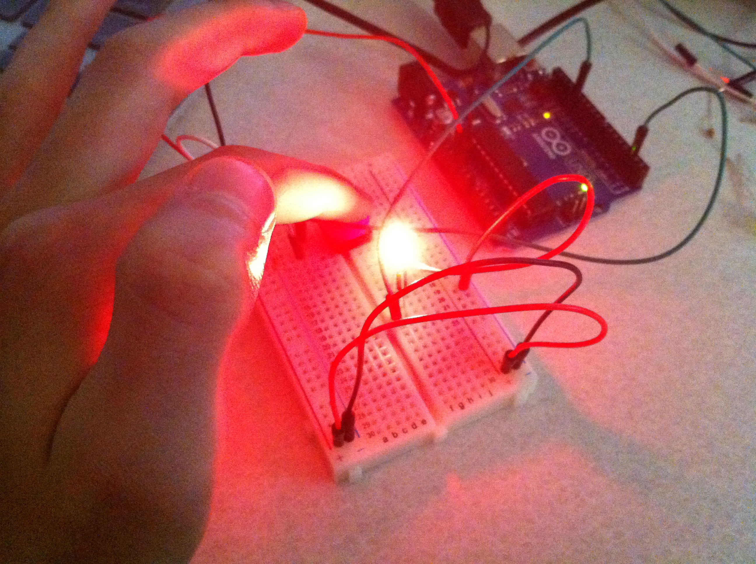
With the help of Marco and Shubs, we were able to make a working pull up circuit! By connecting an LED to pin 13 and creating a pull up circuit that fed to pin 2, we were able to successfully run the Arduino digital “button” example sketch.
Here is the Fritzing sketch that we made during class.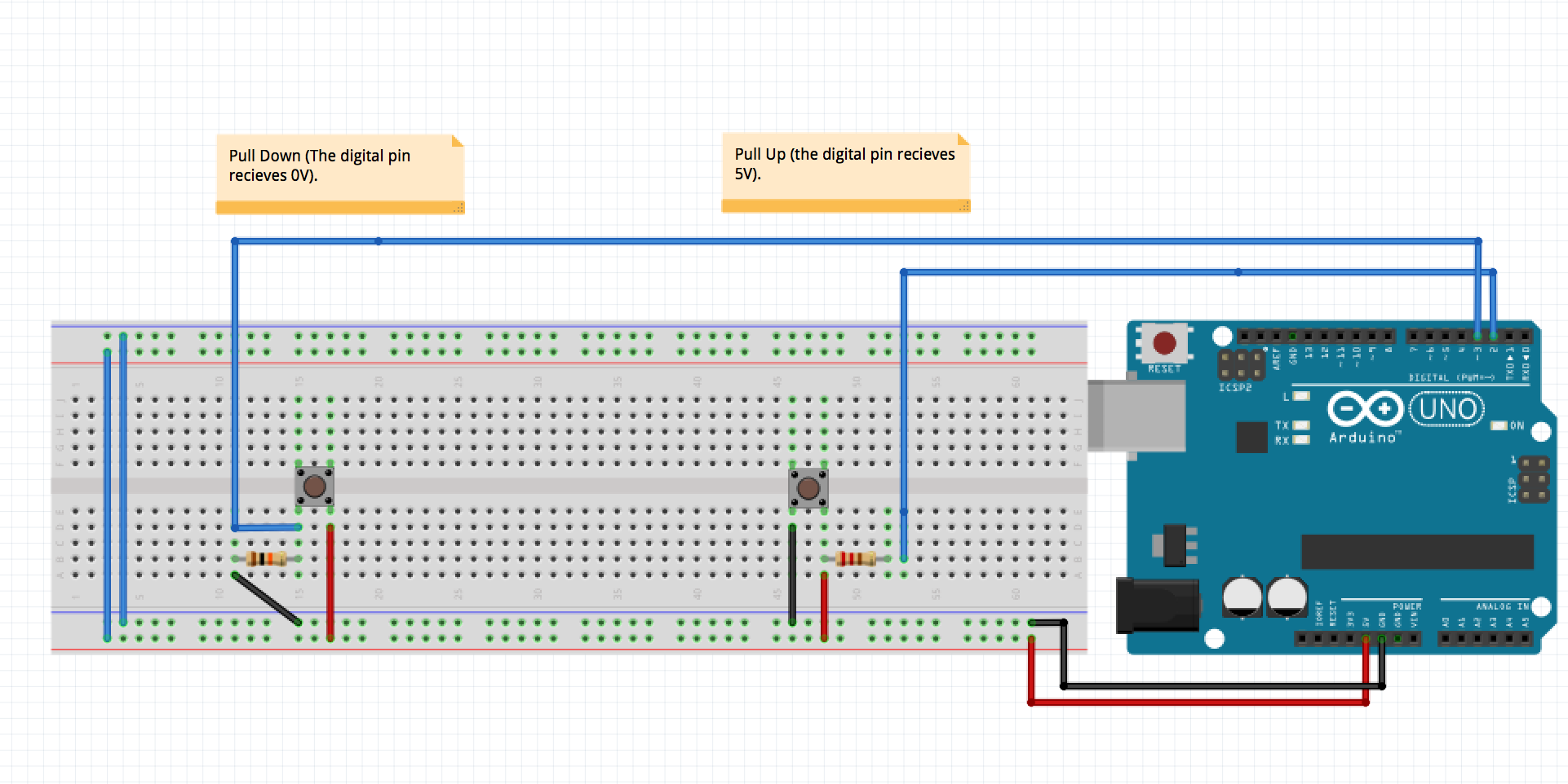
Here is the Arduino digital button program:
// constants won't change. They're used here to

// set pin numbers:

const int buttonPin = 2; // the number of the pushbutton pin

const int ledPin = 13; // the number of the LED pin
// variables will change:

int buttonState = 0; // variable for reading the pushbutton status
void setup() {

// initialize the LED pin as an output:

pinMode(ledPin, OUTPUT);

// initialize the pushbutton pin as an input:

pinMode(buttonPin, INPUT);

}
void loop(){

// read the state of the pushbutton value:

buttonState = digitalRead(buttonPin);
// check if the pushbutton is pressed.

// if it is, the buttonState is HIGH:

if (buttonState == HIGH) {

// turn LED on:

digitalWrite(ledPin, HIGH);

}

else {

// turn LED off:

digitalWrite(ledPin, LOW);

}

}