[Lab: Environment] LED Matrix 8×8

brightness

IMG_2637

IMG_2638

IMG_2642


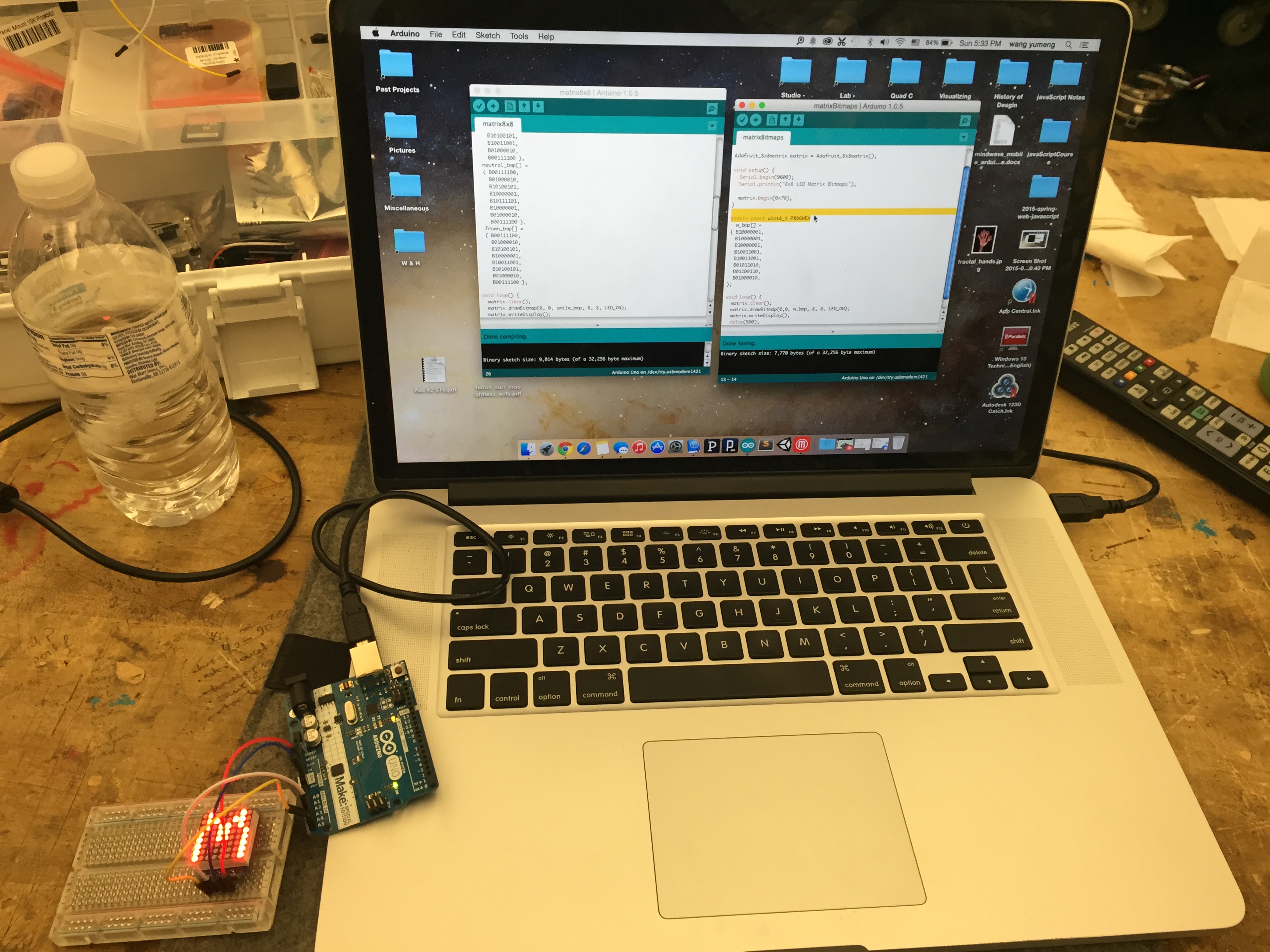
In class, we soldered the 8×8 LED matrix onto its driver board, both from Adafruit. We downloaded the two libraries from Adafruit and ran the examples in Arduino IDE. In the code, the LED matrix is divided by lines, and for each line there is 0 for off and 1 for on. Therefore, we can easily create our own patterns. What is even more helpful is the functions already written in the library, which enabling us to directly type letters or common shapes like circles and rectangles. The most interesting part for me is probably the brightness function that I can set from 0 to 16. So I put it inside a for-loop with a slight delay in the end. Then the LED matrix starts to breathe/blink (click the first picture to see gif).


Here is the code for the blinking circle:

#include <Wire.h>
#include “Adafruit_LEDBackpack.h”
#include “Adafruit_GFX.h”

Adafruit_8x8matrix matrix = Adafruit_8x8matrix();

void setup() {
Serial.begin(9600);
Serial.println(“8×8 LED Matrix Bitmaps”);

matrix.begin(0x70);
}

static const uint8_t PROGMEM
w_bmp[] =
{
B10000001,
B10000001,
B10000001,
B10011001,
B10011001,
B01011010,
B01100110,
B01000010,
};

void loop() {
// matrix.clear();
// matrix.drawBitmap(0,0, w_bmp, 8, 8, LED_ON);
// matrix.writeDisplay();
// delay(500);
//
// matrix.setTextSize(1);
// matrix.setTextWrap(false); // we dont want text to wrap so it scrolls nicely
// matrix.setTextColor(LED_ON);
// for (int8_t x=0; x>=-36; x–) {
// matrix.clear();
// matrix.setCursor(x,0);
// matrix.print(“Yumeng”);
// matrix.print(“is”);
// matrix.print(“genius”);
// matrix.writeDisplay();
// delay(100);
// }

matrix.clear();
// matrix.drawCircle(random(0,7),random(0,7), random(1,5), LED_ON);
matrix.drawCircle(3,3, 3, LED_ON);
matrix.writeDisplay(); // write the changes we just made to the display
for (int i = 0; i<=16; i++){
matrix.setBrightness(i);
delay(45);
}

delay(10);
}


[Studio: Environment] Project 1 Description and Issues

Concept:

First, shadows are the reflection of our existence in the space. Then, our shadows overlap, intertwine, communicate. In this project, shadows are turned into subjective representations of our mind states. Instead of being distorted by the source of light, the audience will be able to control their own shadows by wearing the headsets that collect EEG data from them and accordingly form fake shadows projected onto the ground beside them.

For hardwares, this project will utilize a Neurosky Mindwave headset for sensing the EEG data, a laptop to run the Processing sketch for the visualization of the data, and a mini projector to project the visualization/fake shadows.

Challenges:

1. The connection of the EEG headset is troublesome with Mac Yosemite due to software issues. However, it connects on a PC successfully. The current solution is that I use a trial of Parallel to run Windows on my Mac.

2. There are a few Processing libraries to connect the EEG data to the sketch. However, as I tested, none of them work on the new version of Processing. Along with the previous problem, now I’m running Processing 1.5.1 on Windows in order to run the example sketch successfully.

3. Now I’m using the laptop. However, I still want the piece to be wearable, so I want to use a Raspberry Pi instead (if I have enough time). Here are the subsequent issues:

1. I just started setting up my Raspberry Pi and never used it before.
2. The EEG headset doesn’t connect to Linux. I probably still need it to send data to my computer and then use bluetooth or something to send the data to Raspberry Pi? Do you have suggestions for how to do this?
3. I have to install Processing on Raspberry Pi. Will it run very slow?
4. Do you happen to have an HDMI to mini HDMI cable that I can borrow tomorrow in class?
5. Maybe other options to execute the project as a wearable piece?

[Studio: Environment] Reading Response – Thoughtless Acts, Suri

Examples of Thoughtless Acts

In the reading, Suri suggests that good designs are based on the observation of users’ intuitive act to the products or environments. They not only follow the principles of intuitiveness, but also enhance the overall user experience. Thoughtless acts are some of the best inspiration for designers. Here are two examples of thoughtless acts and a witty design to make us conscious about thoughtless acts.

glasses

Putting sunglasses back in the case all the time is inconvenient. Putting them in the pocket will scratch the lens. Hanging them in front of the shirt seems to be easy, convenient, and cool.

kimi

Formula 1 racers have to wear those high-tech fire-proof jumpsuits during the race for their safety. Want to know how uncomfortable those jumpsuits are? After two hours of racing, the drivers essentially take a shower with their sweat inside of the fully-closed capsules. Therefore, the picture above is often seen in the paddock, before and after the race. The racer (Kimi Raikkonen!) takes off the upper part of the jumpsuit and wrap it around the waist to be comfortable. Maybe it is also the racer’s fashion to wear jumpsuits this way.

rain

This instance is a witty reminder of how important thoughtless acts can be. No one will doubt that when it rains, we hide ourselves under shelters to stay away from the rain. The designer uses hydrophobic paint to paint on the cement ground. It is invisible during sunny days, however, when it rains, the caption shows: “Stay dry out there.”


[Lab: Environment] Labduino

breather

(Click on the picture to see the gif.)

The LED breather example from class uses a PWM pin to simulate an analog output to dim the LED. AnalogWrite actually still uses digital output, but controls the percentage of the time of on or off to make the pseudo analog output. (analog output)

I found a reference to make the real analog output buy connecting a capacitor to filter the voltage during on or off, in order to average the voltage. http://arduino-info.wikispaces.com/Analog-Output

IMG_2551

Force resistive sensor controlling a servo motor (analog input – digital output)

photo 3-1

Sound impact sensor controlling a stepper motor (digital input? – analog output)

Meanwhile, the serial monitor prints out the input as 1 or 0. (Serial output)

Screen Shot 2015-02-09 at 12.40.53 PM

A serial in sketch to help the use choose between coffee and tea. (Serial input)


[Lab: Environment] LabDuino Work in Progress


For the first part of the LabDuino, we connected a photocell, as the analog input, and an LED, as the digital output, and made the LED dim according to how much light the photocell was exposed to. (Unfortunately I forgot to take a picture of this part.)

For the second part, I connected a force resistive sensor to a servo. Same problem appeared as before: the servo shakes all the time, due to the fast fluctuation of the analog input. After class, Michael helped me to solve this problem by sending the average number of 150 input values to the servo, so that it will move more smoothly. I understood the logic of this part, but we did not succeed yet with the new modified code. Hope we can fix it in next class.

IMG_2551


For the next, I can’t wait to use the parts that I have not used before, such as joysticks, accelerometers/gyros, LED matrixes, etc.