Project 2: beyond metrics

ah42

The above image is known as the data pyramid. raw data is held at the bottom, the stuff that can be collected from the environment. Up at the very top lies choice, making a decision based on the data, information and knowledge presented with.

Tasked with collecting personal data with the intention to later induce a change in habit, I listed many types of metrics that I could collect.

  • number of times I sit down
  • hours spent vs standing vs walking
  • number of times I eat
  • number of times i move my jaw per day
  • number of breaths i take in a day
  • how many times I check facebook
  • number of conversations per day
  • number of tabs that I open
  • number of times I pick my nose
  • number of times I bite my fingernails
  • money spent/day
  • number of yawns
  • The status of my poop
  • emotional state at a given moment
  • stress level at a given moment
  • hours spent inside vs outside

The list continues, but those were a few of the many. Of that list, I chose to collect the number of conversations I have per day because I felt it had greater personal significance to myself. I feel as if I don’t talk that often, but was curious to find out how many times I actually strike up a conversation on a given day. With the behavior psychologist, Pavlov in mind, I thought I’d attempt to change my conversation behavior.

IMG_1911

IMG_1935

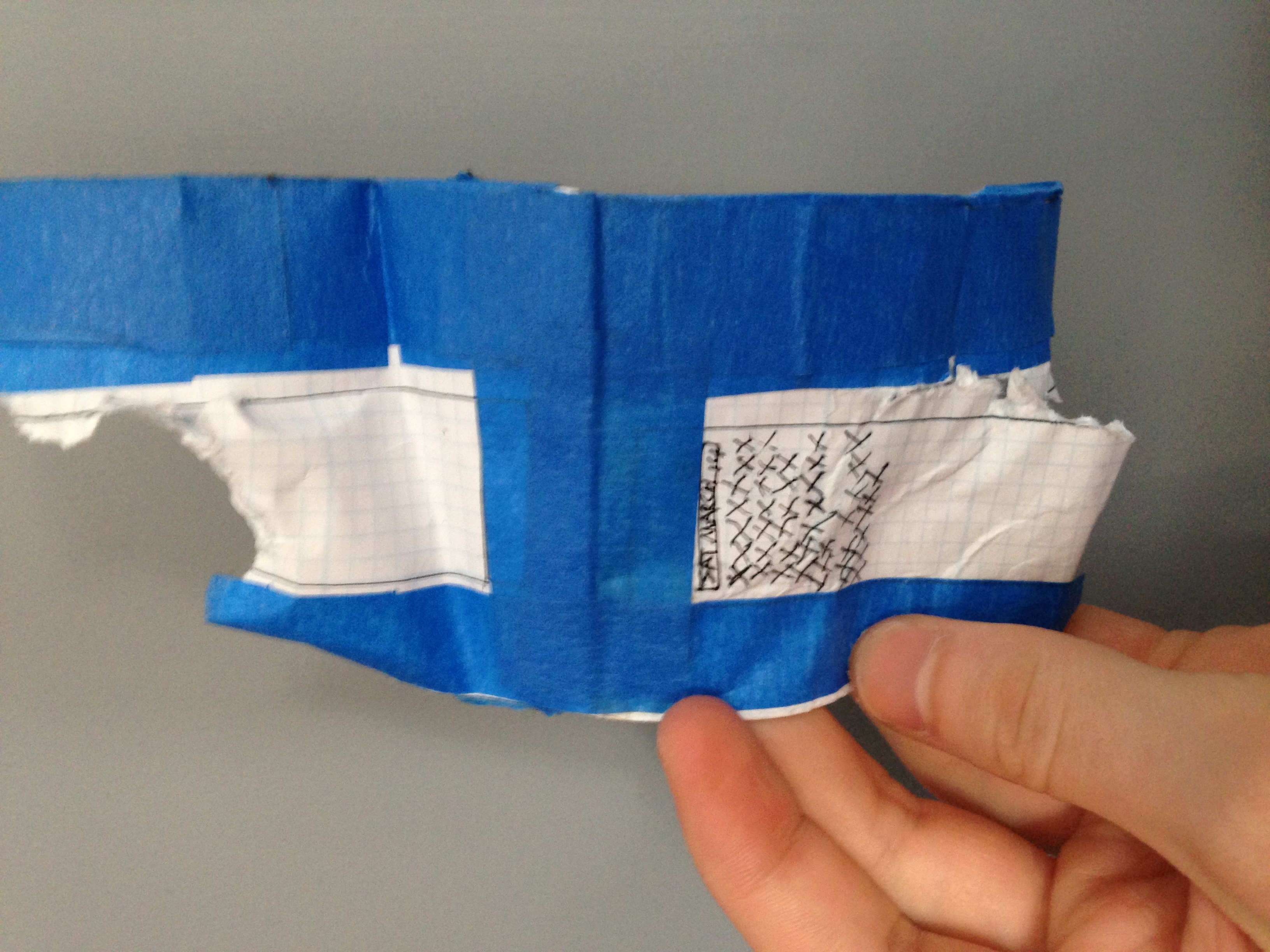
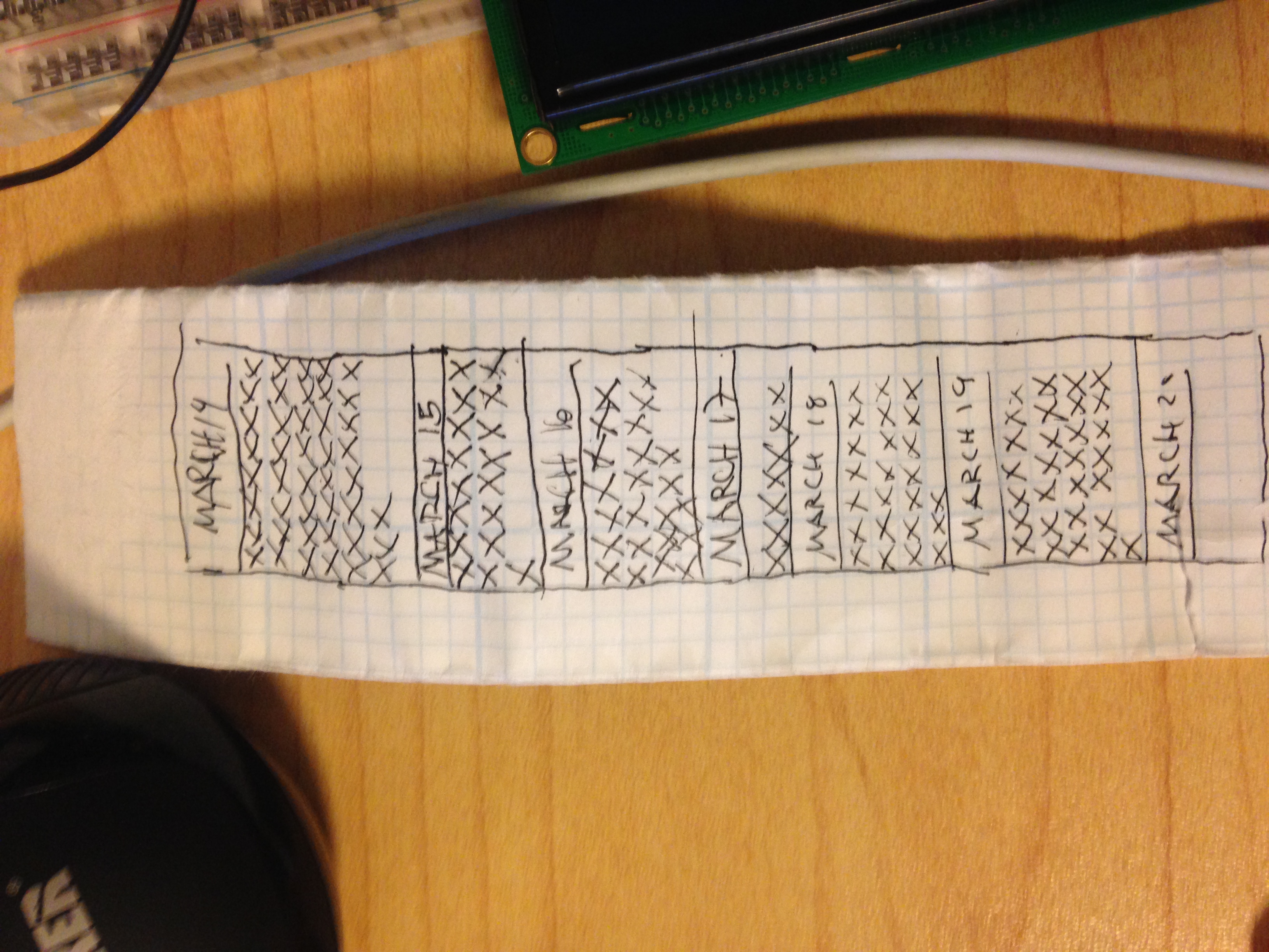
I created a simple wrist bracelet that I could log conversations with by marking it with a pen. This method was semi-effective, though definitely not the most accurate way to collect the data because it relied on me first, having a pen on hand at all times, second on me actively pulling out the pen mid conversation to mark it, and third on making the band every day(it disintegrated in the shower on the second day). But it more or less got the job done and I was able to see fluctuations in the amount of conversations I had over the course of a week.

Project 1: Testing R820T dongle w/ Pi Again

I was able to get the program to run on the raspberry pi after finding a very helpful google groups thread on this error:

Kernel driver is active, or device is claimed by second instance of librtlsdr.
In the first case, please either detach or blacklist the kernel module
(dvb_usb_rtl28xxu), or enable automatic detaching at compile time.

SUPER HELPFUL!
Dongle connection error solved: claimed by second instance of librtlsdr

I typed:

sudo rmmod dvb_usb_rtl28xxu

and it unmounted the dvb portion of the dongle, or whatever was preventing it from connecting in the first place.

Im also using a slightly different dongle:
KEEDOX® RTL-SDR, FM+DAB, DVB-T USB Stick Set with RTL2832U & R820T.

Additionally I installed all of the neccessary libraries/dependancies for aplay to work (which is absolutely a must because it is used to process the radio real time and output audio).

full install guide here.

The ALSA utilities:
sudo apt-get install alsa-utils

MP3 tools:
sudo apt-get install mpg321

WAV to MP3 conversion tool:
sudo apt-get install lame

Also set the audio to analog output because I was using headphones:
sudo amixer cset numid=3 1

I tuned to the station suggested by http://sdr.osmocom.org/trac/wiki/rtl-sdr
rtl_fm -f 96.3e6 -M wbfm -s 200000 -r 48000 – | aplay -r 48k -f S16_LE

CPU is running below 30% while listening.

Project 1: using the R820T SDR & DVB-T dongle on Mac OSX

Setting up the R820T SDR usb dongle on a mac is relatively straight forward thanks to the hard work of Alain de Carolis who neatly packed all the dependancies and libraries into a DMG, ready to use out of the box (sort of). With this program there is also a small issue when hooking up the R820T. After opening up the server connection upon launching GNU Radio – borip_server, and subsequently running HDSDR, you need to change the device hint to RTL, not RTL e4k. Unfortunately, this failed the second time launching the program so I was forced to reinstall the DMG and go through the same process.

After getting the program to succesfully connect with the dongle, some noise should be heard. No official documentation has been put out by HDSDR, but because it is a free, open source software, there is a community built up around it to support. I went through this documentation and watched a few youtube videos. The program itself is fairly straight forward and the documentation is built in a way that lets you click on any area of a screenshot to bring up its description.

In order to receive the signals, an antenna is needed. The antenna provided by the kit is a monopole antenna, but I found it to be pretty much useless. All I could receive was static noise. I even attempted hacking together a dipole antenna from RadioShack, but to no avail.
IMG_1859

IMG_1858

IMG_1859

IMG_1860


The next step to get a clear signal will be trying to install the libstl made by Steve-m onto my mac and run it through terminal. Updates to come.

Project 1: hooking up the R820T SDR with the Raspberry Pi (Wont work)

In order to turn the R820T into an SDR (software defined radio) device, a number of programs need to be installed on the Raspberry Pi.

First of all, git needs to be installed on Pi. An easy install onto Debian can be done through terminal by typing in “$ apt-get install git”. If permission is denied, type “$ sudo apt-get install git” to initialize as superuser, which essentially overrides all permission.

Before jumping in, I wanted to learn what all these commands were, specifically “make”. I learned that make has a long history in linux. It is essentially a package compiler and installer. After downloading a repo, make must be used to build the app out. A great intro to make is here.

Also, before starting, its a good idea to update Raspbian with “sudo apt-get update” and after that, type: “sudo aptget install cmake buildessential pythonpip libusb1.00dev pythonnumpy git”

This will install the libusb repo, which to my understanding is what allows communication with the dongle.

After that, I followed adafruit’s installation commands for the stl-sdr library for interfacing with the dongle. The library they suggested to clone is:
In a fresh terminal window, type these commands exactly.
cd ~
git clone git://git.osmocom.org/rtl-sdr.git
cd rtl-sdr
mkdir build
cd build
cmake ../ -DINSTALL_UDEV_RULES=ON -DDETACH_KERNEL_DRIVER=ON
make
sudo make install
sudo ldconfig

After that is installed, it is important to copy the rtl-sdr.rules file to /etc/udev/rules.d
I did this by opening up a terminal window from the rtl-sdr folder and typing: “sudo cp -i rtl-sdr.rules /etc/udev/rules.d”. The cp command takes two inputs, the file you wish to copy, followed by the directory path you wish to paste it to.

Finally, to test the R820T usb dongle. In a fresh terminal window, type sudo rtl_test -t. Theoretically, this should open up a connection with the dongle and start spitting out a frequency or at least show some data. Unfortunately for me, this was not the case. Instead I recieved a nasty error. It successfuly found the device, but it gave me a “usb_claim_interface error -6” and the device fails to open.

A great conversation about this issue is found on a post to hamradioscience.com. The specific thread is here.

When using the R820T, people consistently reported having the same issue. Some people suggest using an externally powered usb port, because the dongle may draw to much energy from the Pi.

Alternatively, I tried installing a fork of the original library that is more up-to-date. Unfortunately, this didn’t solve anything. It seems to be a hardware problem.

TL;DR The R820T dongle wont work on the Raspberry Pi unless it is externally powered (i have yet to test that, so i cannot confirm). Instead, people suggest using the 2832u E4000 chip, which is, unfortunately, not as finely tunable as the R820T. Hopefully someone will find a fix for this.

Project 1: Connecting to the internet

Connecting to the internet with a raspberry pi required some trial and error. In order to connect to the network you need all the right configurations set for the specific network, otherwise it will always fail to connect.

Steps I took to connect:

  1. Hook up one of the compatible wifi usb sticks with your raspberry pi after you have booted up.
  2. go to the wifi configuration under preferences in the main menu inside of the Debian GUI.
  3. go to the manage networks tab and scan for available networks.
  4. once you have found a network, press add.
  5. The SSID is the name of the network
  6. To determine Authentication, Encryption, and EAP method, open up system preferences on your mac, go to network, and find the same network you are attempting to connect to with your raspberry pi, I was connected to “newschool”. It should describe the EAP authentication method next to “Authenticated via …” where it will show one of the many methods. On the raspberry pi, select that EAP method, mine was “PEAP”. For Authentication, you will need to go into advanced settings where it will list the name of the network along with its security. Mine was “WPA2 Enterprise”
  7. In raspbian network gui, go back to the current status tab and connect. It will take a moment. Once connected it will say complete
  8. open up a Midori window and type something in!

Adafruit 8X8 LED matrix

870-00htt

The Adafruit 8X8 matrix conveniently comes with the their GFX library which makes it increadibly easy to create shapes and animations on the 8×8 led grid.

Before making any visuals, some soldering is required to get the matrix running and working with the Arduino. The tutorial can be found here.

As a group between Zanzie,Kim, and I, we were able to make several simple bitmap images and animations.

Project 1: moving forward with RaspberryPi

In order to receive police radio signals and output the data to an Arduino, A few options were presented to me.

Originally i wanted to be mostly dependent on hardware, meaning that I would use a traditional radio setup with a tuner. Sparkfun’s Si4702 FM radio reciever board looked promising until I read the datasheet. The chip can’t tune to frequencies above 108MHz FM. Unfortunately Manhattan precincts all broadcast well above that frequency – mostly broadcasting above 400 MHz. 🙁

A few alternatives were brought to my attention.

1.) I could use a Raspberry Pi (which i have no previous experience with) and SDR usb dongle to pick up on specific frequencies, that could later be output to an Arduino via an audio jack that would oscillate between 0V and +5V.

2.) I could purchase a premade radio scanner and hack it to fit my project. Such scanners can be found on EBAY. A list of top of the line hobby radio scanners are here.

3.) A more advanced radio tuning chip is in the making that would likely give me the reception I need. the chip is capable of receiving between 50 MHz and 1000 MHz!! This range is astounding… but it looks like it is still in development. If and when it comes out, this chip could come in handy.

At the moment, I am using Raspberry Pi and SDR.
I am currently running Raspbian. I have purchased and am waiting for:

  • wireless mouse and keyboard
  • dvi to hdmi converter
  • SDR usb dongle and antenna
  • BNC female to MCX male dongle
  • mini haptic motors

Once I have received those I will:

setup the Raspberry Pi with the RTL2832U SDR usb dongle. For that I will need follow this Raspberry Pi forum post on setting it up through command line.

Utilize the documentation on how to use what is called demod.

If I can get past that I will move onto getting audio output from the Pi.

Beyond that, will be the next steps of the project.

  • set up communication with Arduino
  • make haptic components respond according to the audio
  • design the hoodie and integrate the electronic components

Project 1: next steps

In order to receive police radio information, parse it, and output a response to another device, like an Arduino and create the wearable, I will need to complete these two tutorials:

Adafruit’s raspberry pi SDR police radio scanner guide comes with a list of components needed to turn a raspbery pi’s computing power into a radio.
https://learn.adafruit.com/freq-show-raspberry-pi-rtl-sdr-scanner/overview

and

A nice instructables guide shows that it is possible for an Arduino to read radio frequency! It’s quite the hacky process because Arduino can only read between 0V and +5V, there are a few steps to transform the radio wave to fit. This combined with the raspbery Pi, and i should be able to hook up some vibration motors to place around the hoodie to create haptic feed back for the wearer.
http://www.instructables.com/id/Arduino-Audio-Input/step2/Prepare-audio-jack/

Project 1 initial steps

The project:

I will make a wearable device in collaboration with my previous suitemate and founder of K2O, James Halls Collins. The first version of the wearable will be an iteration of their “BADMAN” hoodie. Electronics will be integrated into the hoodie so that it will be able to pick up on police radio frequencies within the Brooklyn/Manhattan area.

The goal:
In response to recent events culminating from Ferguson, Missouri the wearable seeks to create greater balance between police and citizen – particularly providing wearers of the hoodie with the advantage of a live instrument for detecting police proximity. The hoodie will translate the radio waves into some sort of haptic or visual feedback mechanism embedded within the garment that will give the perception of proximity.

I have already received James approval to move ahead with the project.

next steps:

figure out a design for the hoodie based on the components I will be using.

Determine what technologies i need in order to interface with hertzian space.

A few items I have come across that i am considering/doing research on:

Software Defined Radio

conductive thread

Neo Pixel

Arduino Uno, Lillypad or Adafruit Gemma

EL Wire

fiber optic fabric