After the midterm review, the structure I had in mind changed significantly to be more coherent in terms of where program is located and what the space intends for patrons to do both above and below. I wanted to maintain the core spatial relationships I established throughout the semester, but I had to “reel in” the form enough that it could be understood easier.
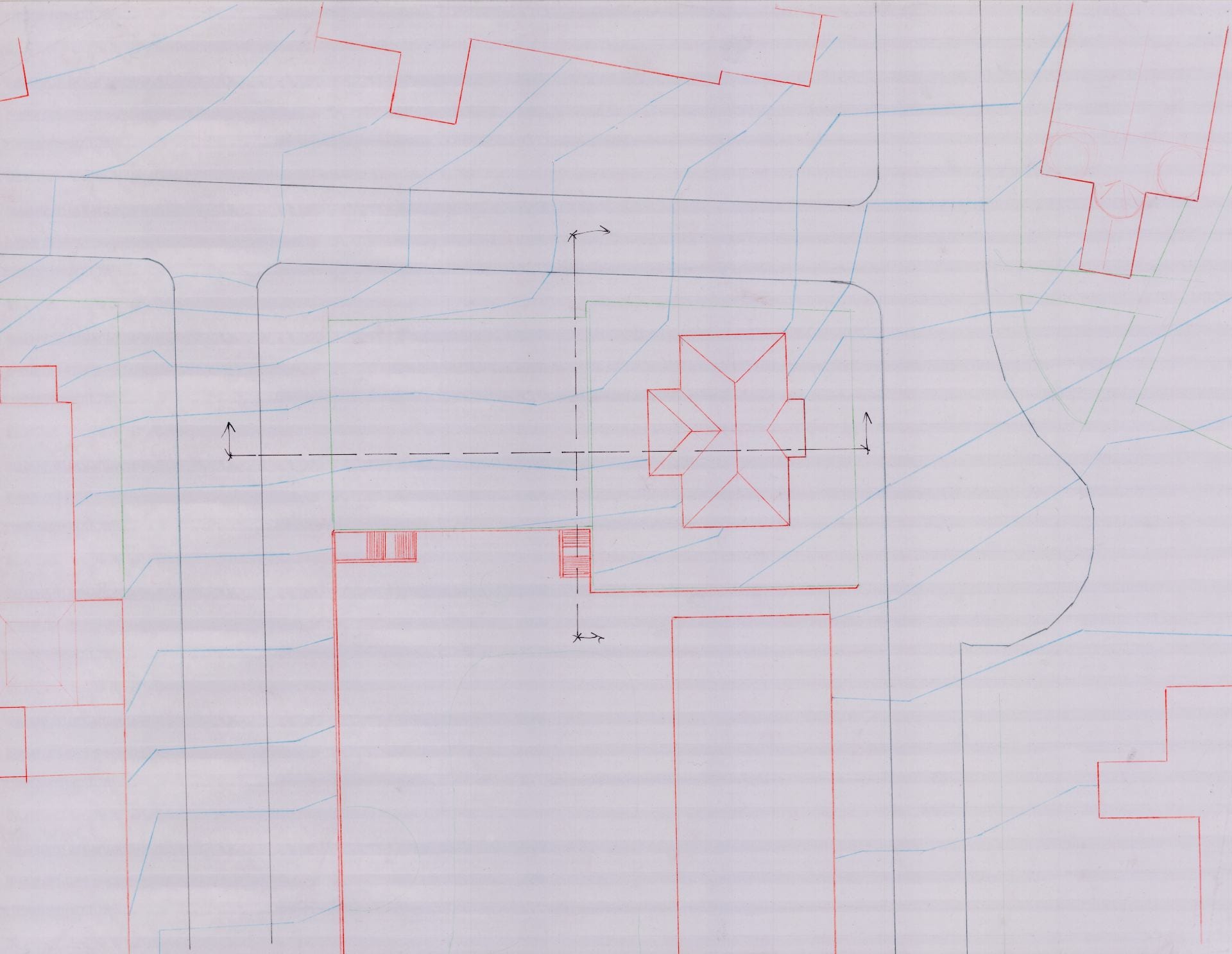
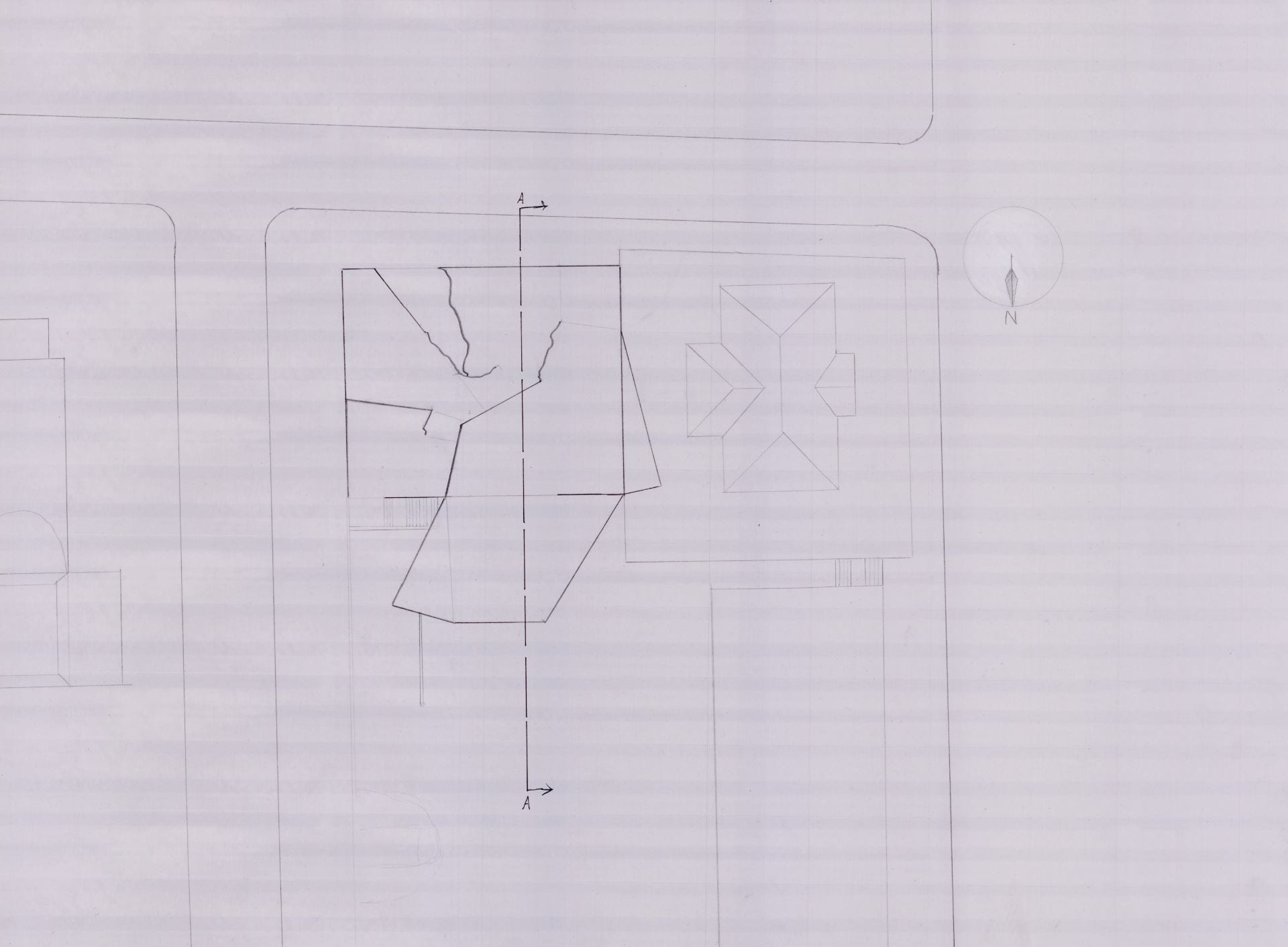
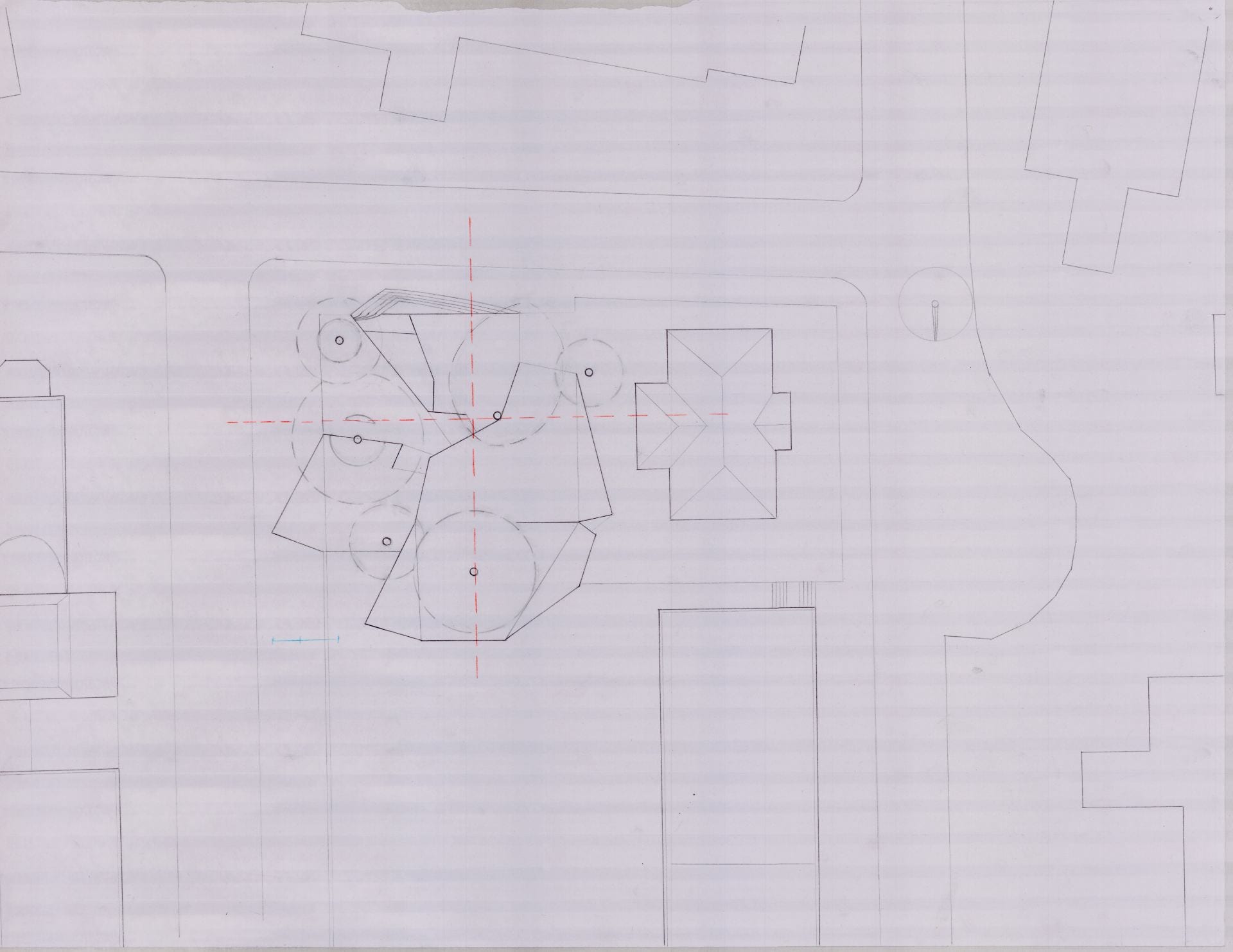
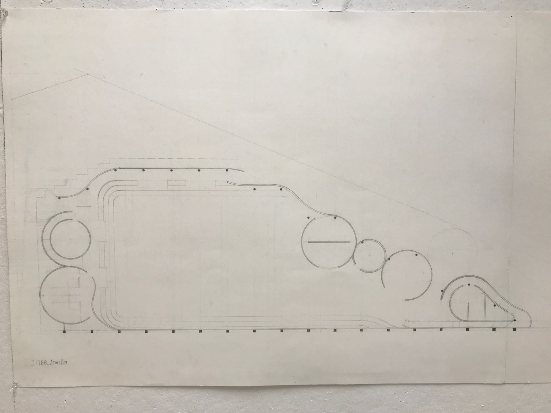
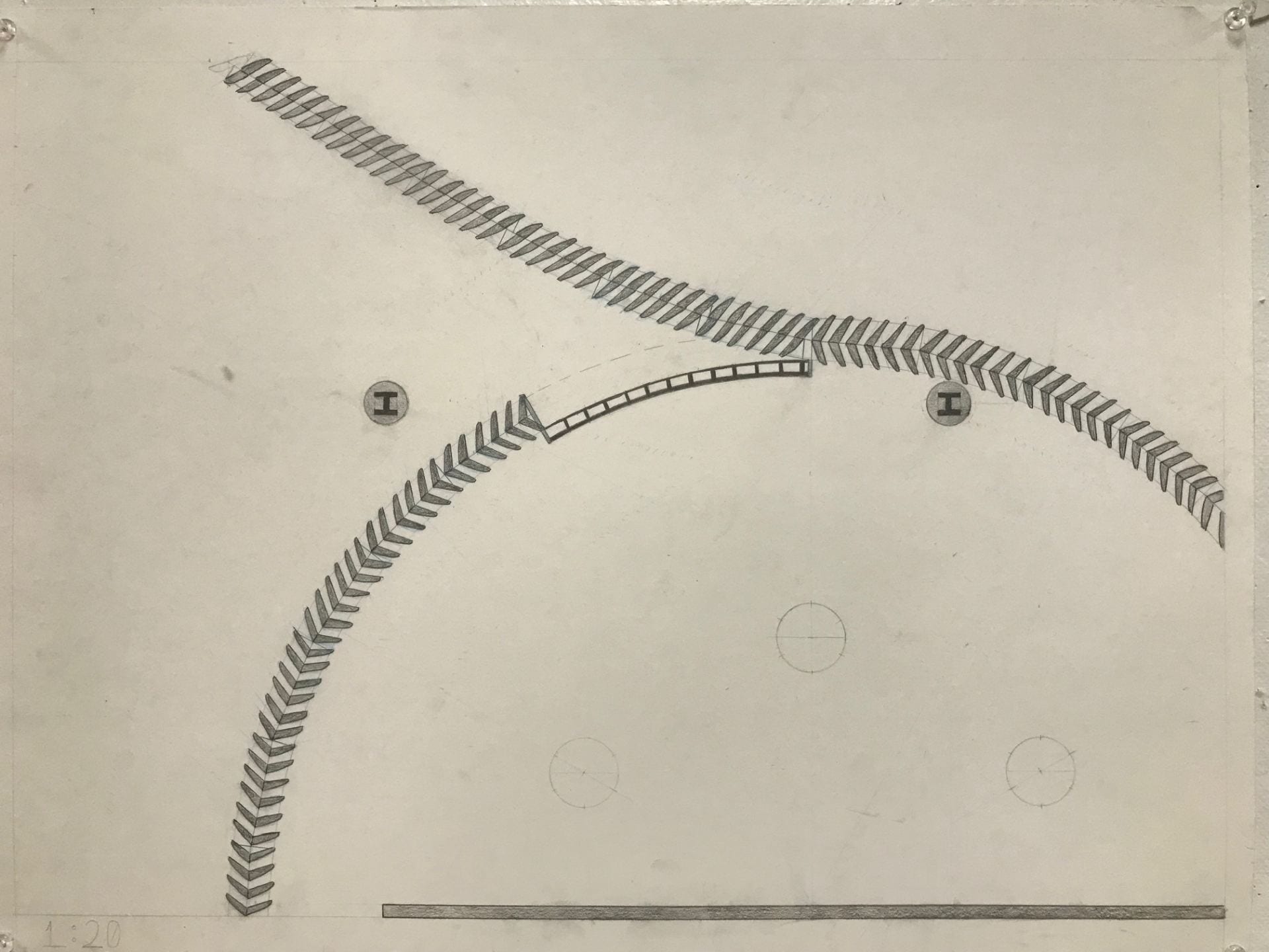
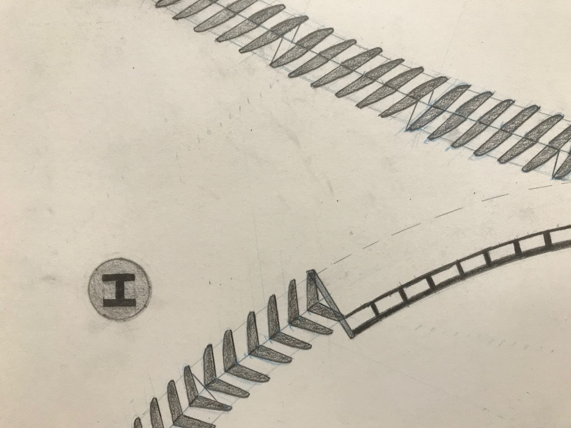
1:20 site drawing

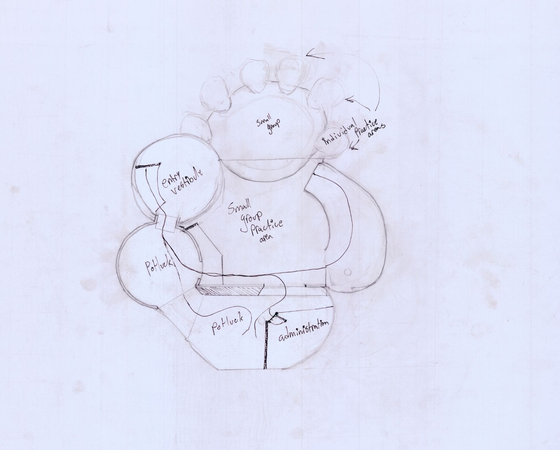
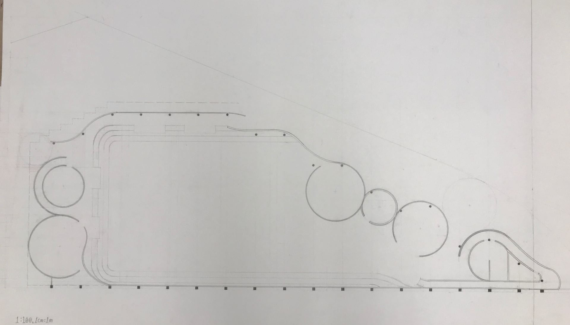
Plans
starting from bottom to above:


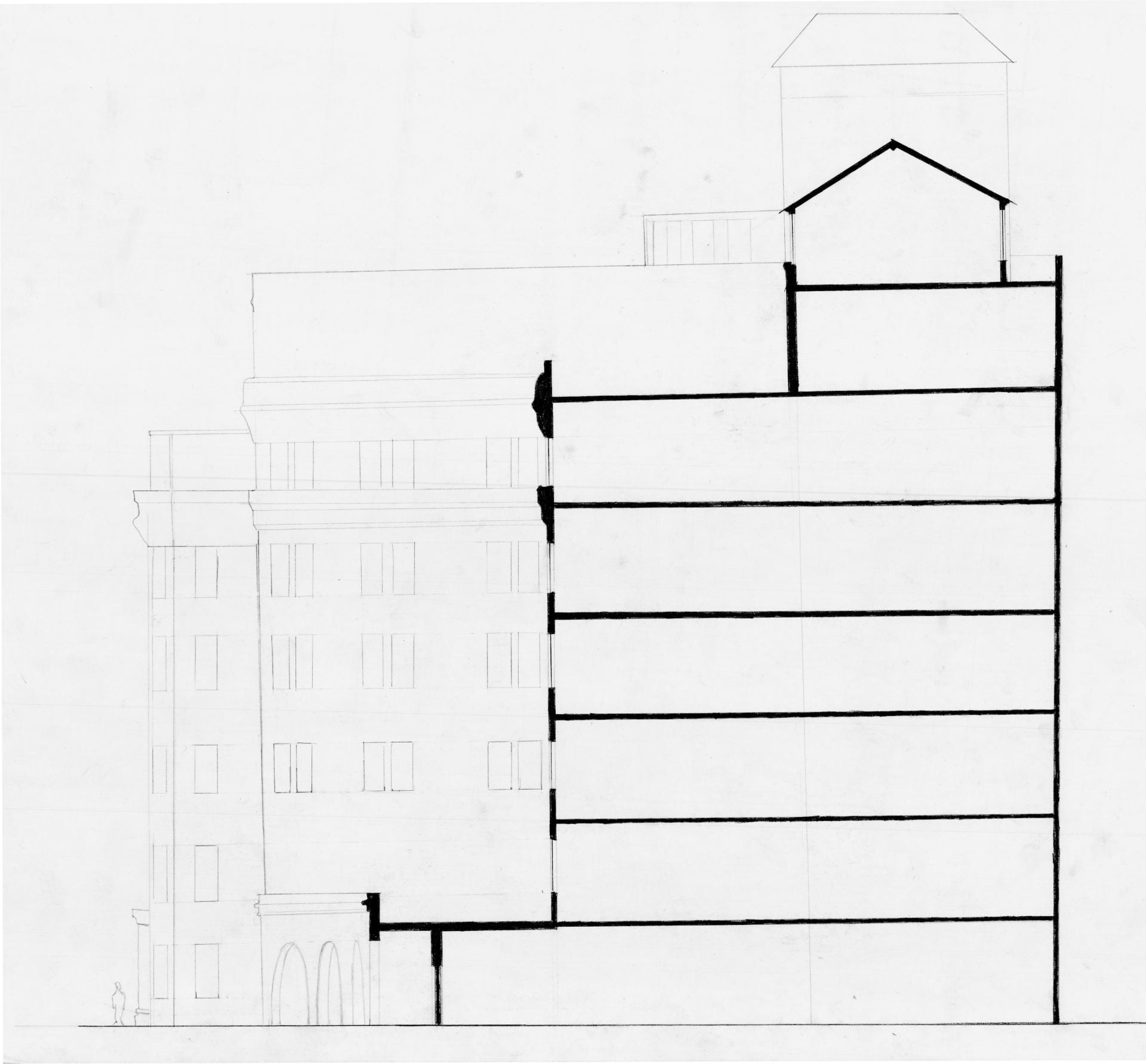
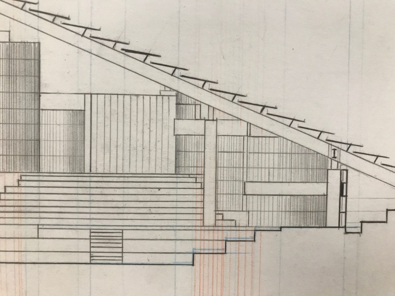
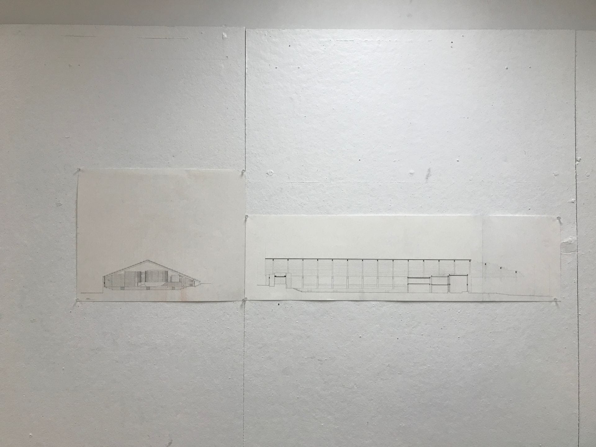
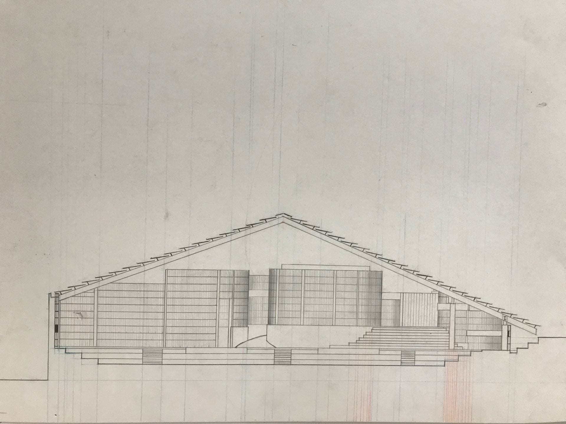
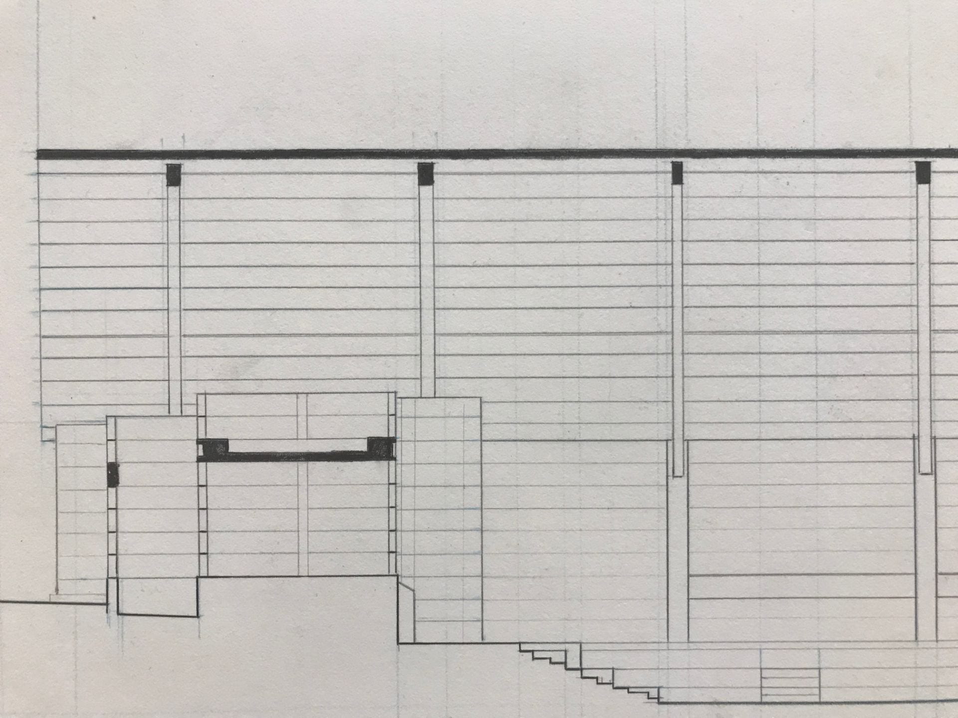
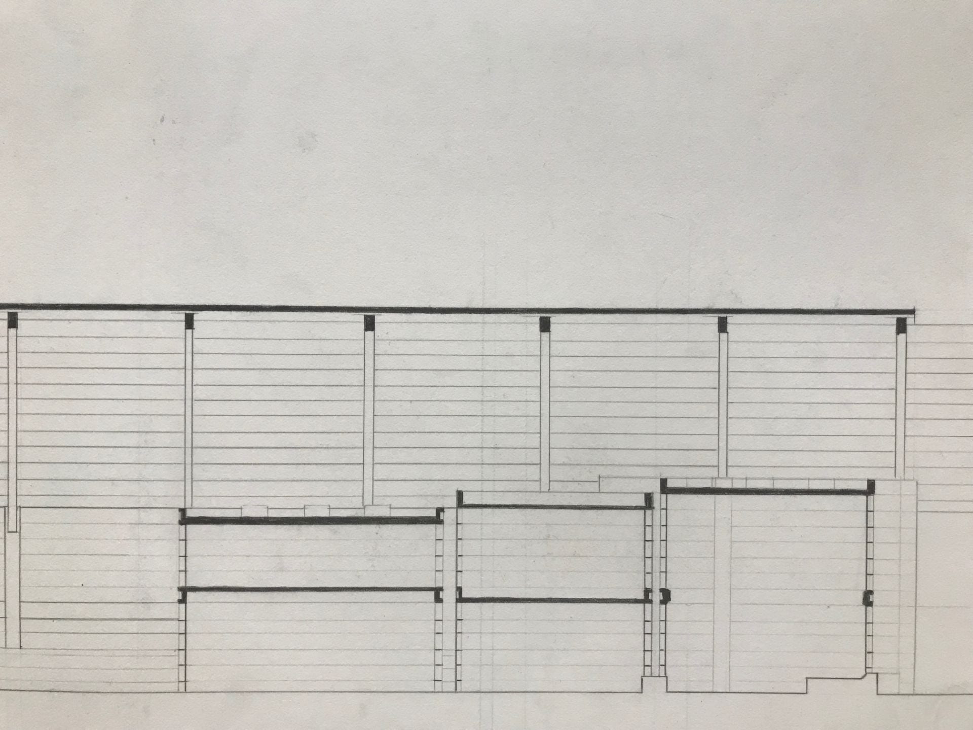
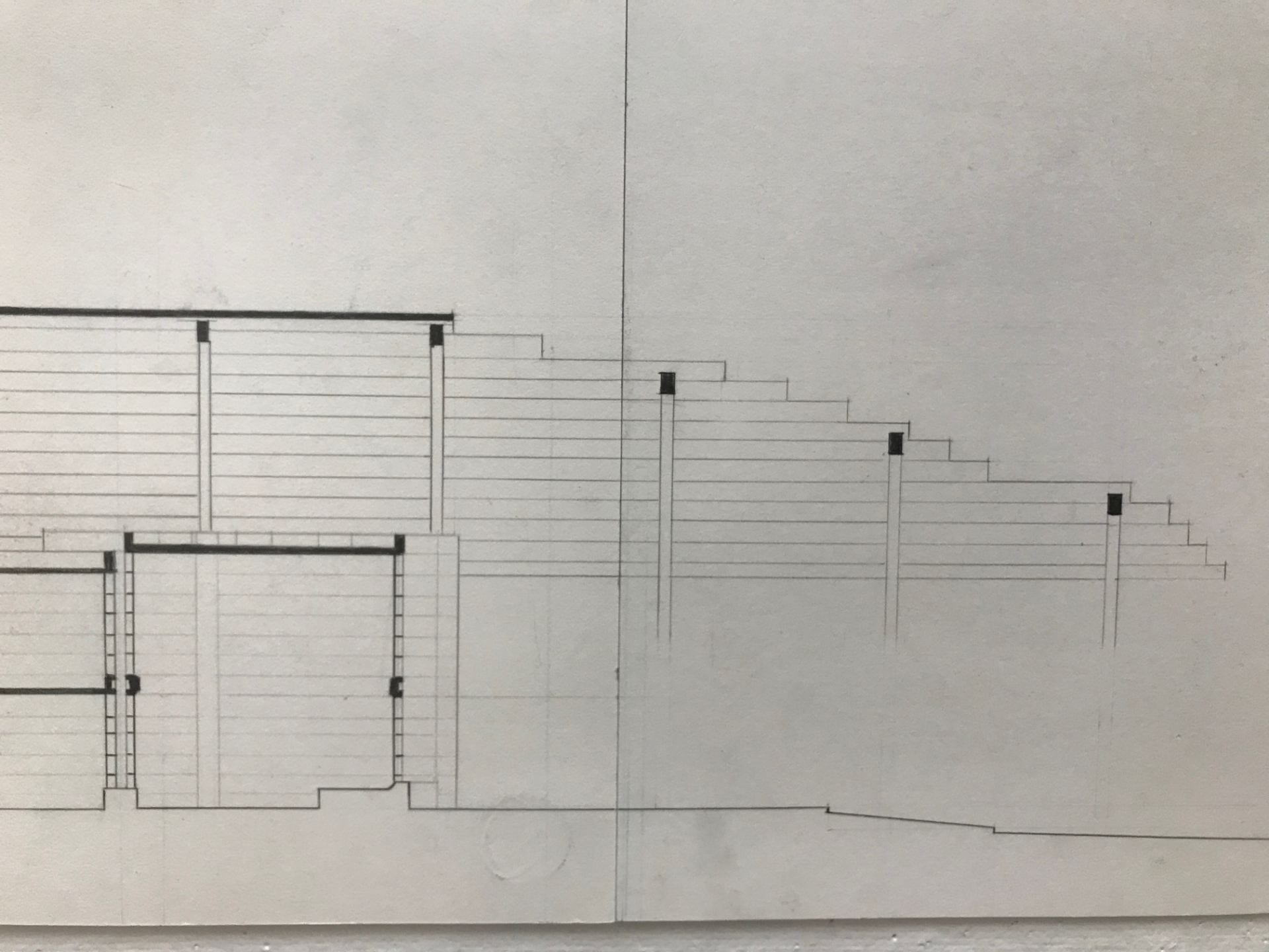
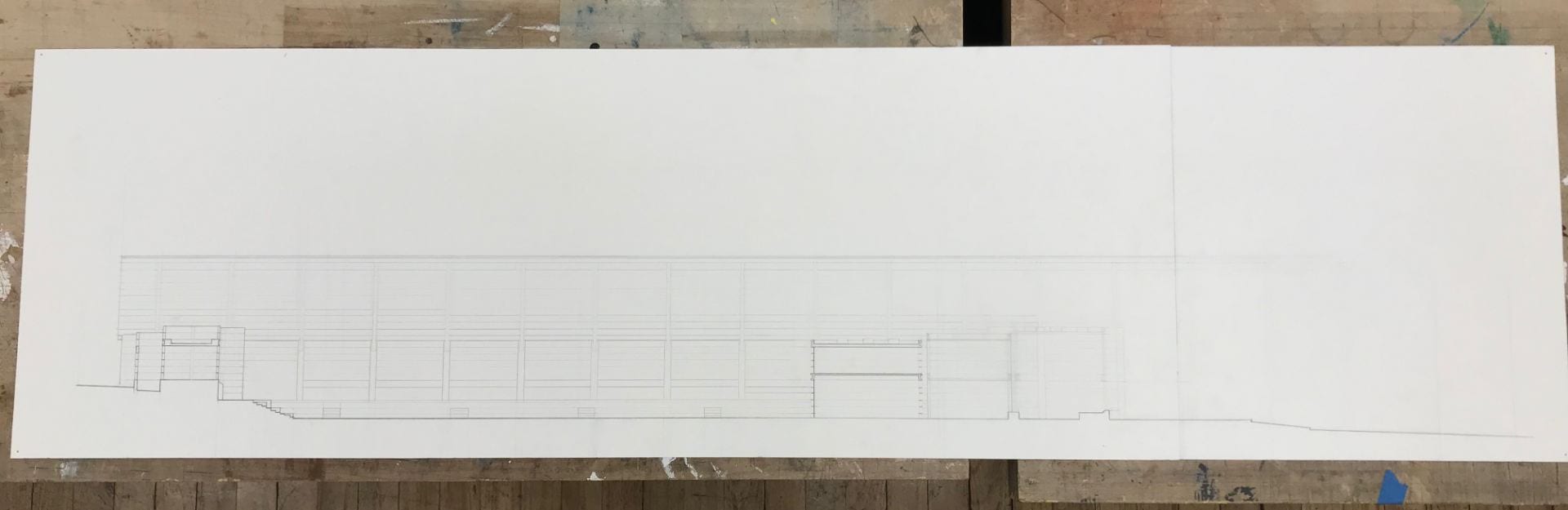
Sections
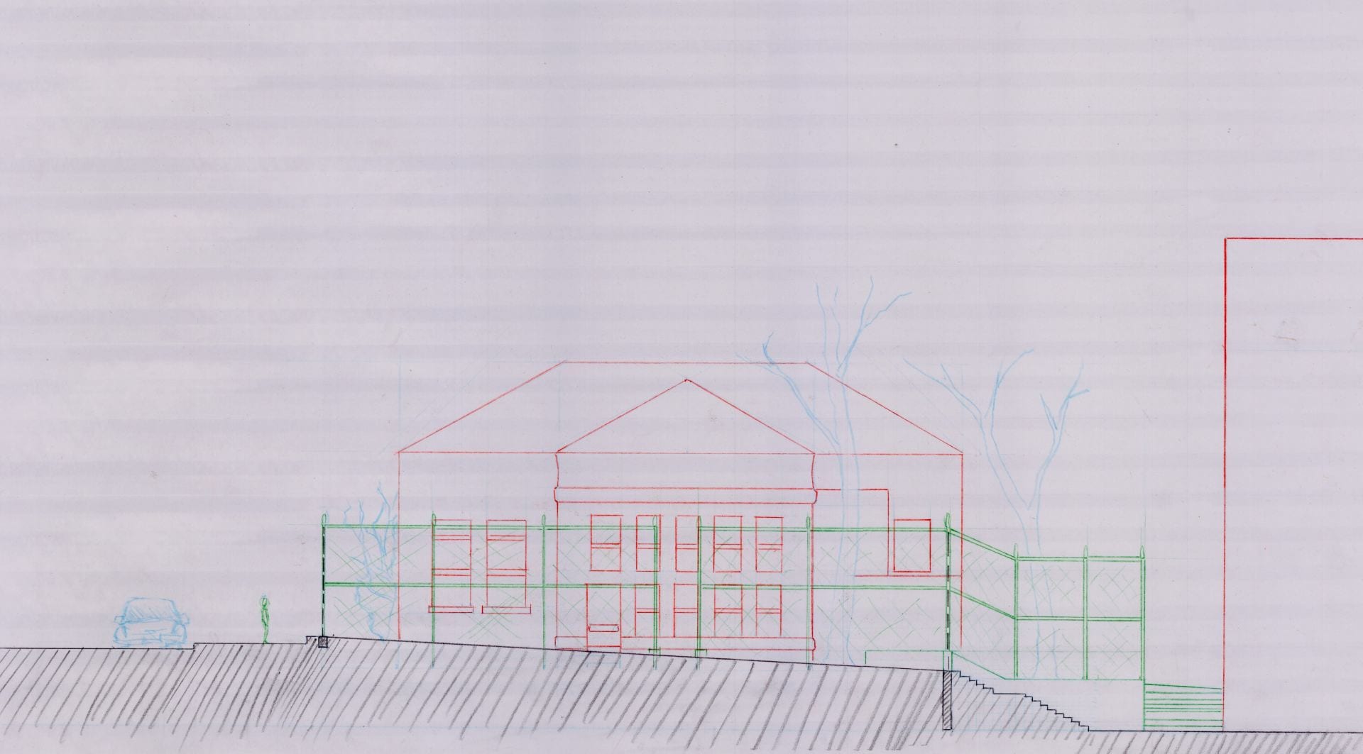
context: section through playground and sidewalk, front entrance, Auburn Assessment center in the background
context: a cut through the site and library, ingersoll housing complex in background
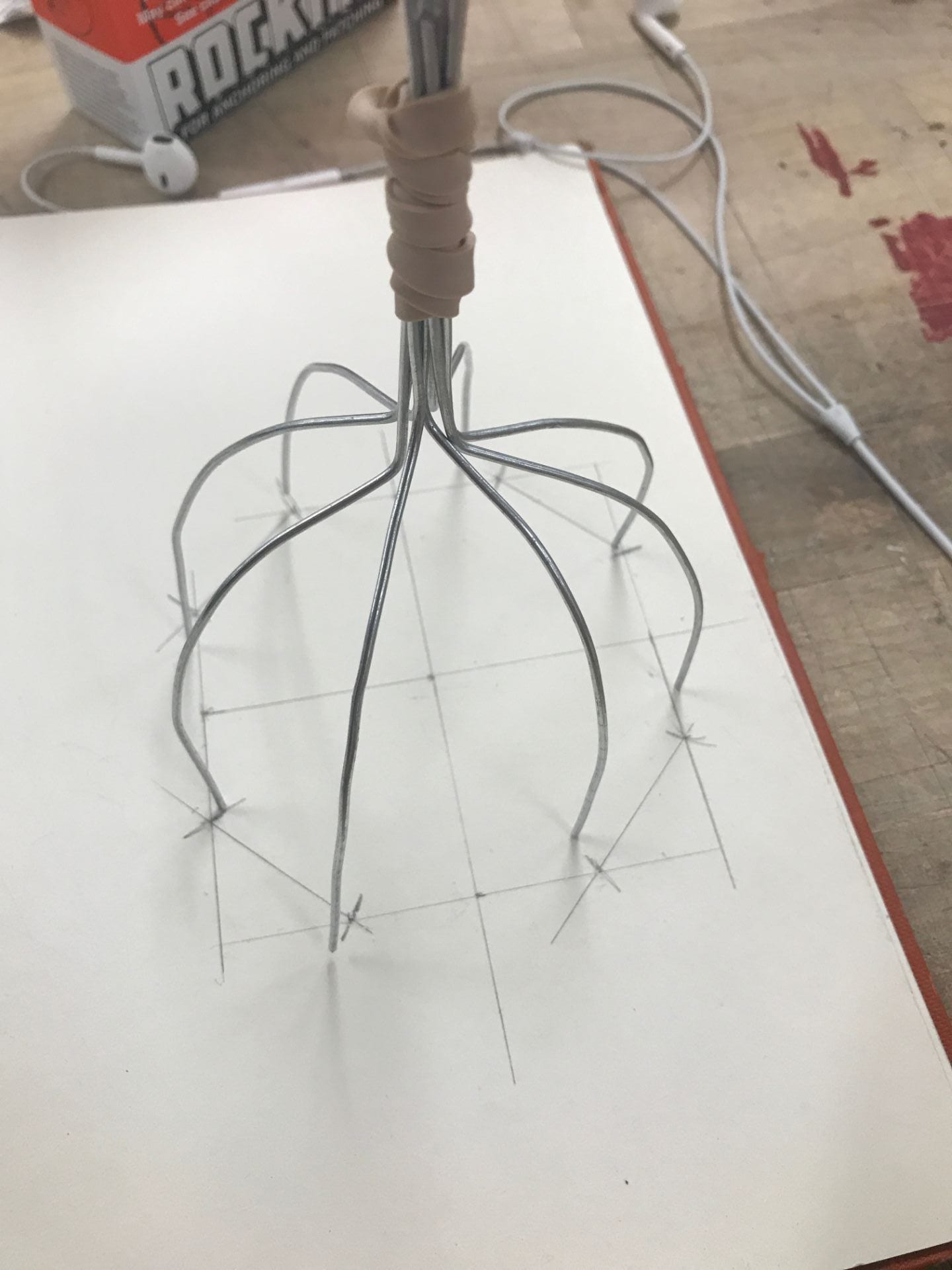
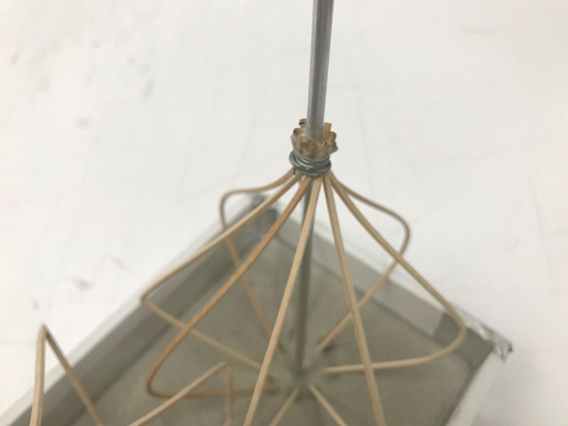
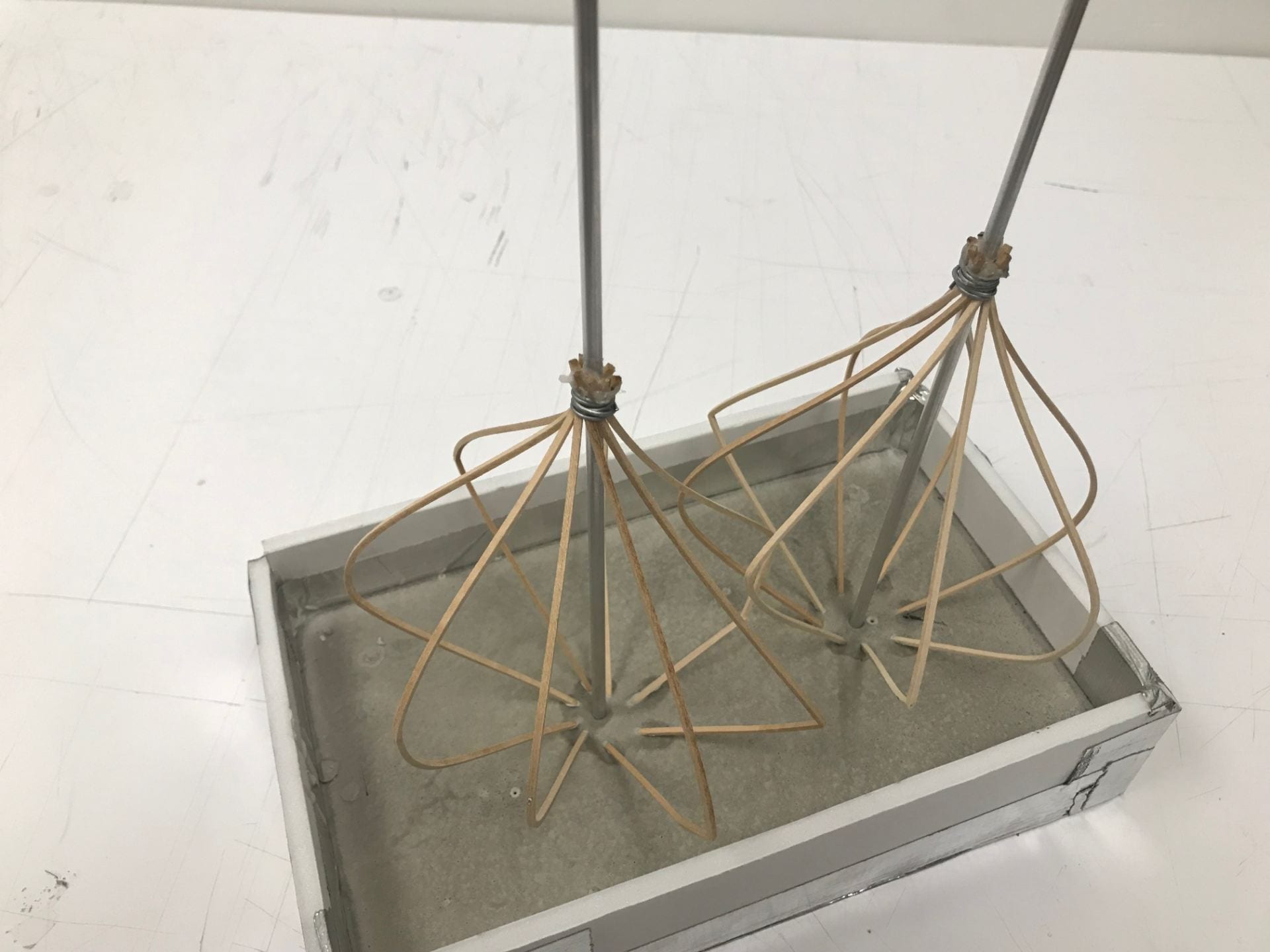
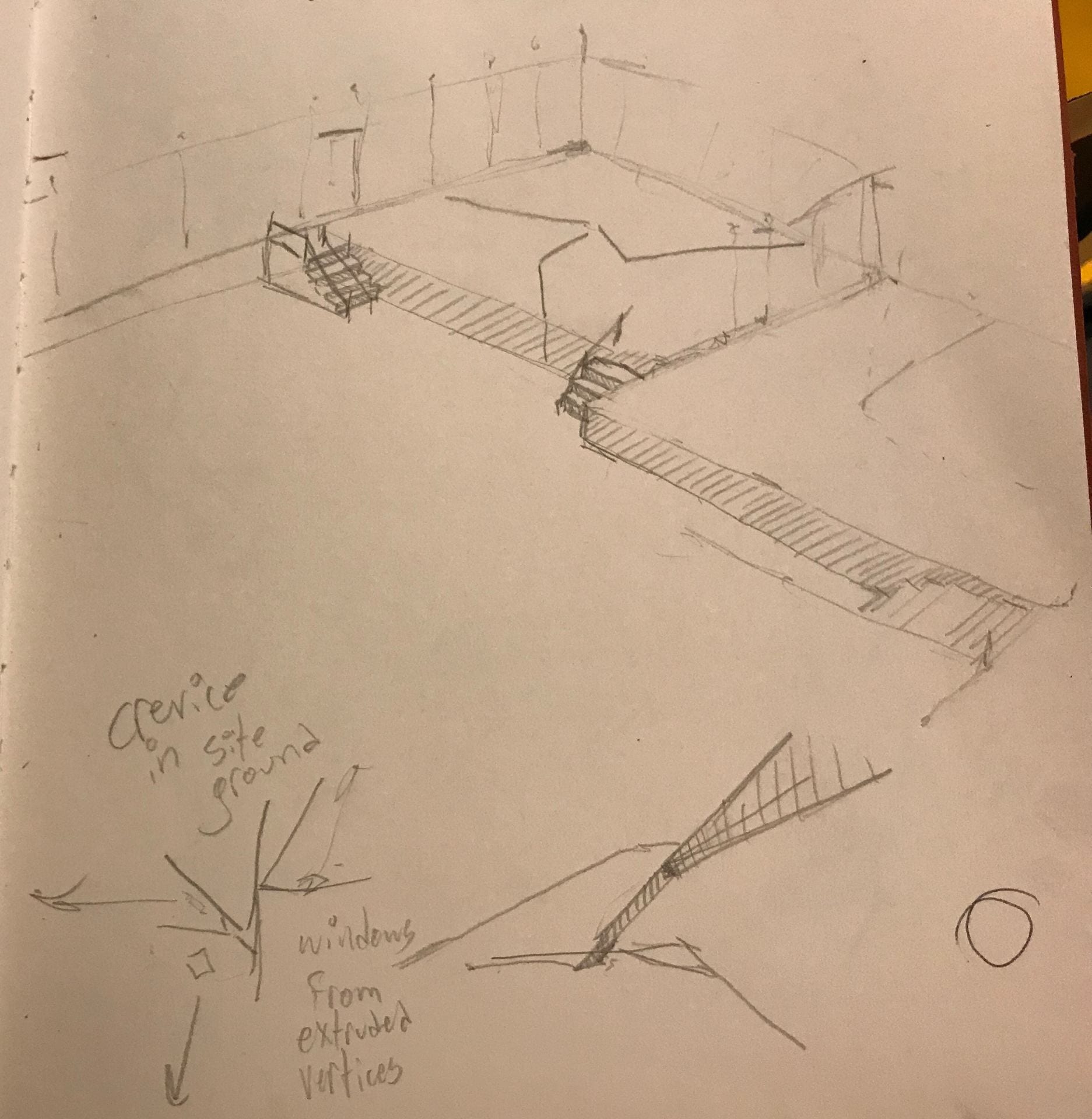
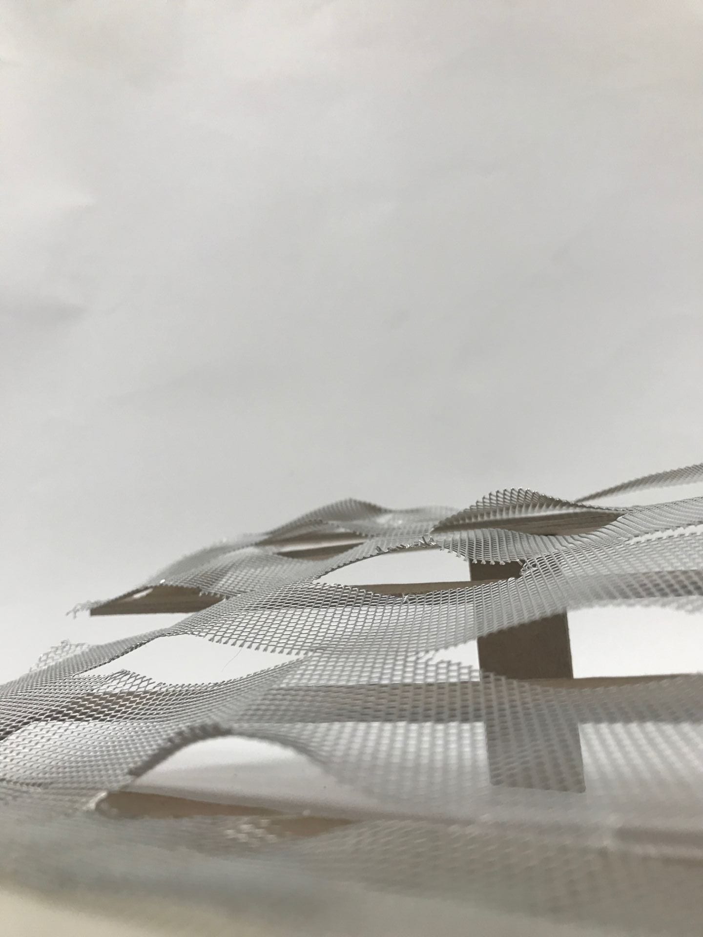
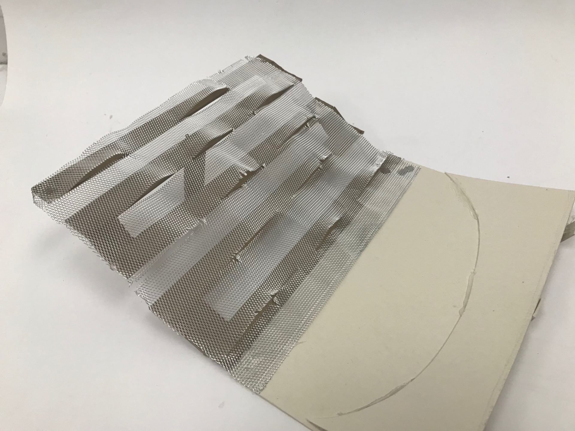
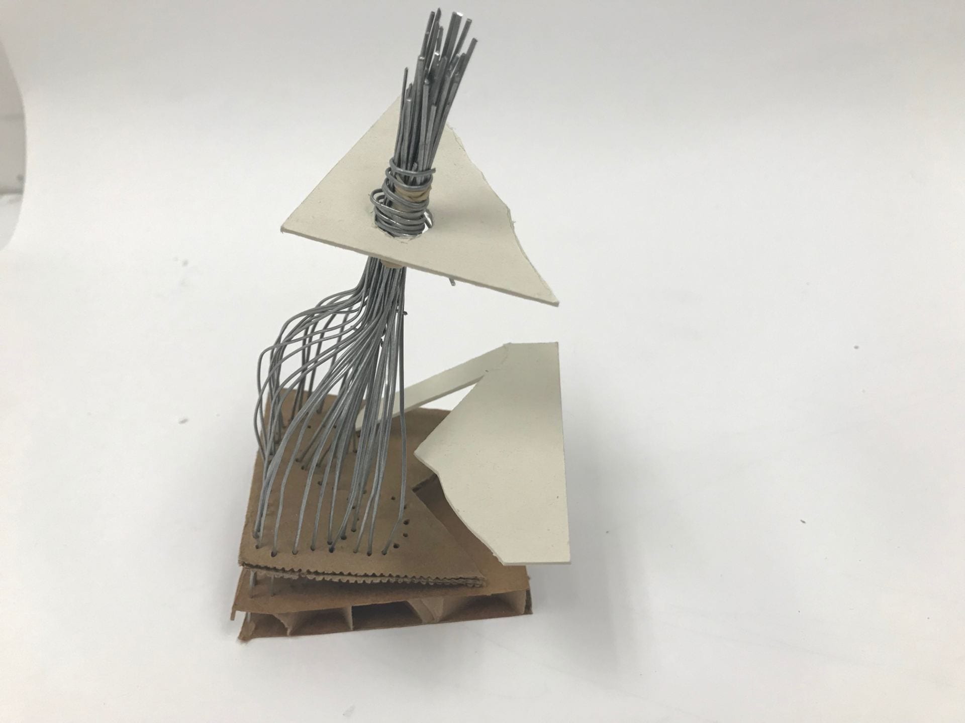
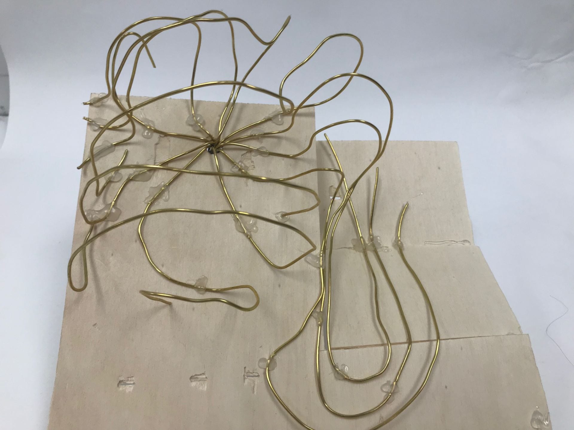
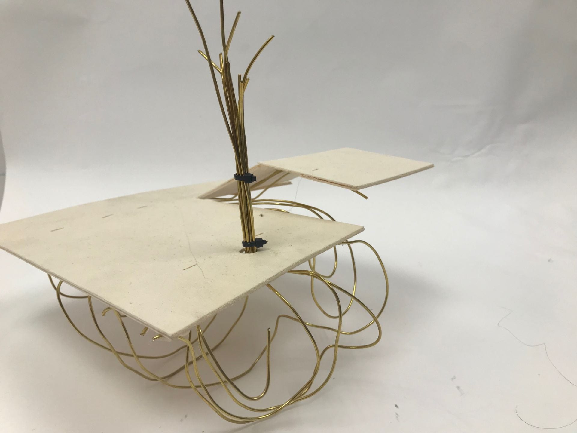
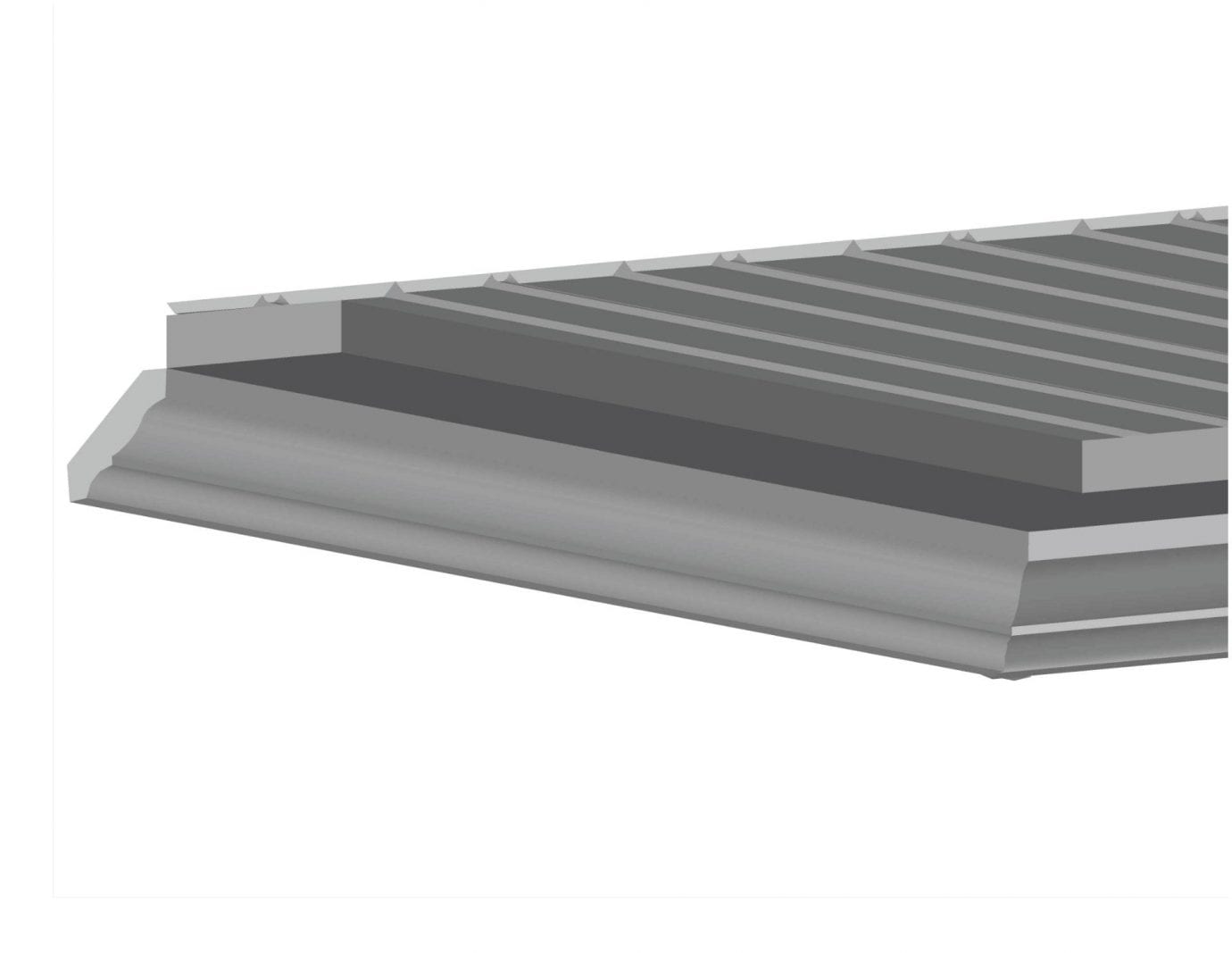
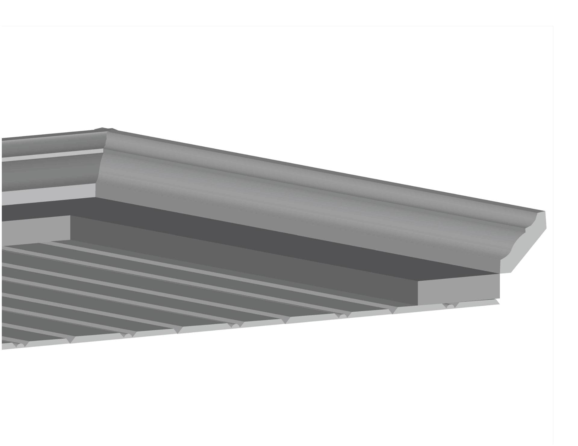
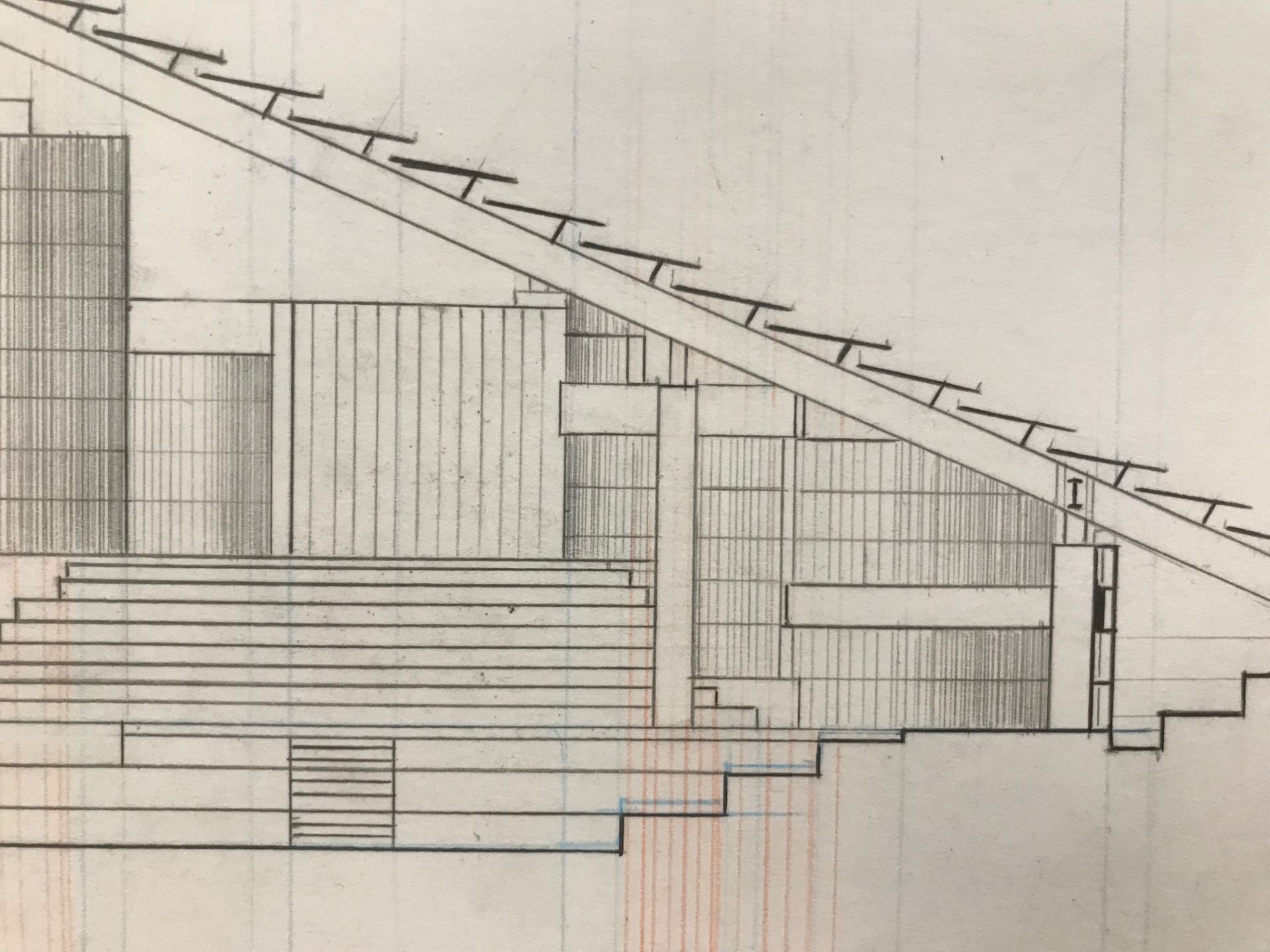
Detail Drawing of pod system:

Diagram of the panel-to-pod fiber optic system

The panels that reach above the surface bring natural light into the pods and underground space by using fiber optics.
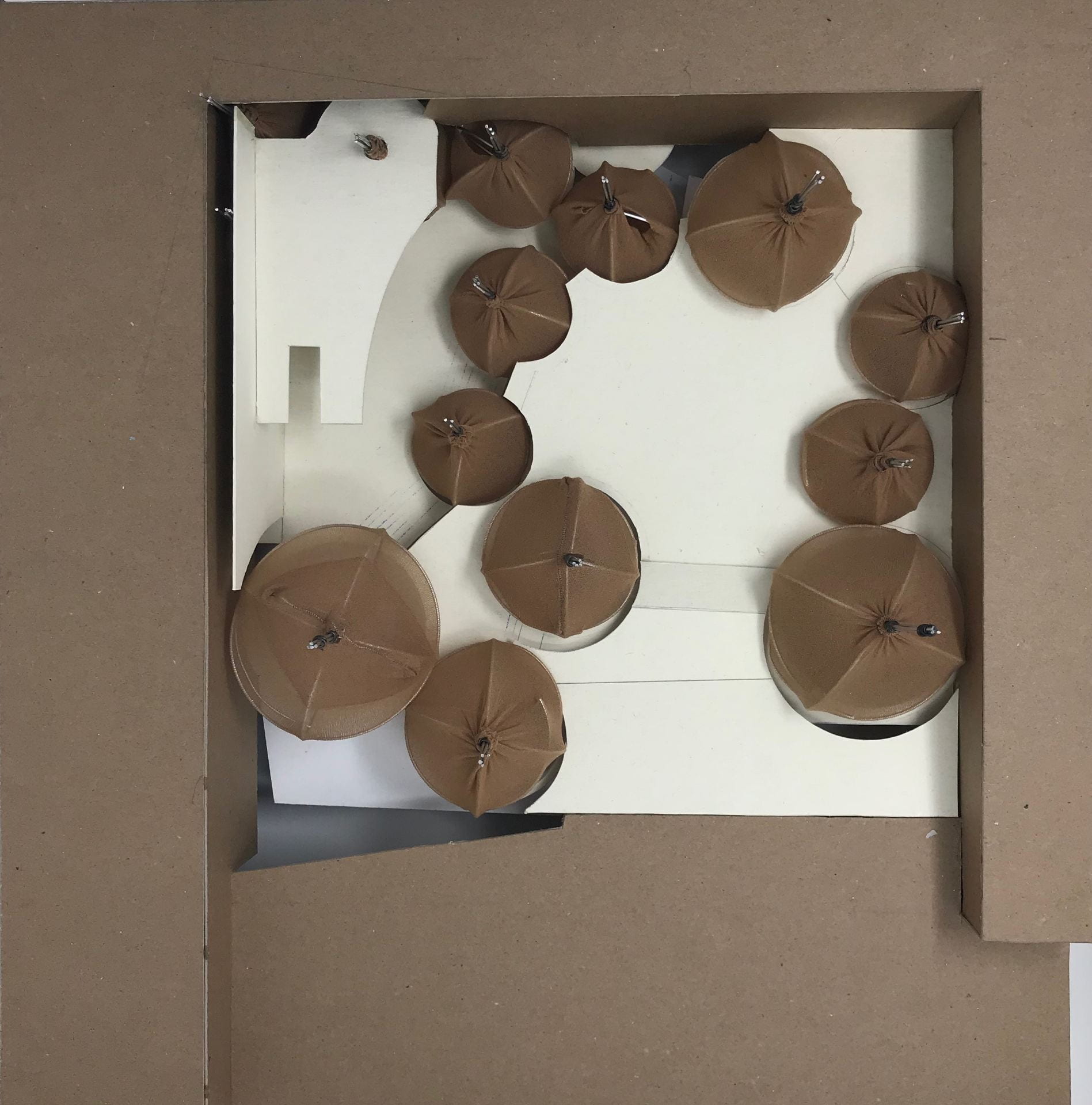
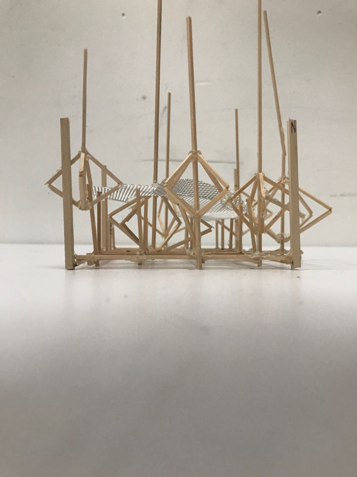
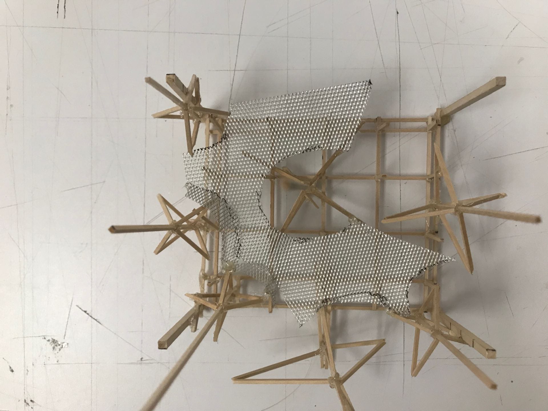
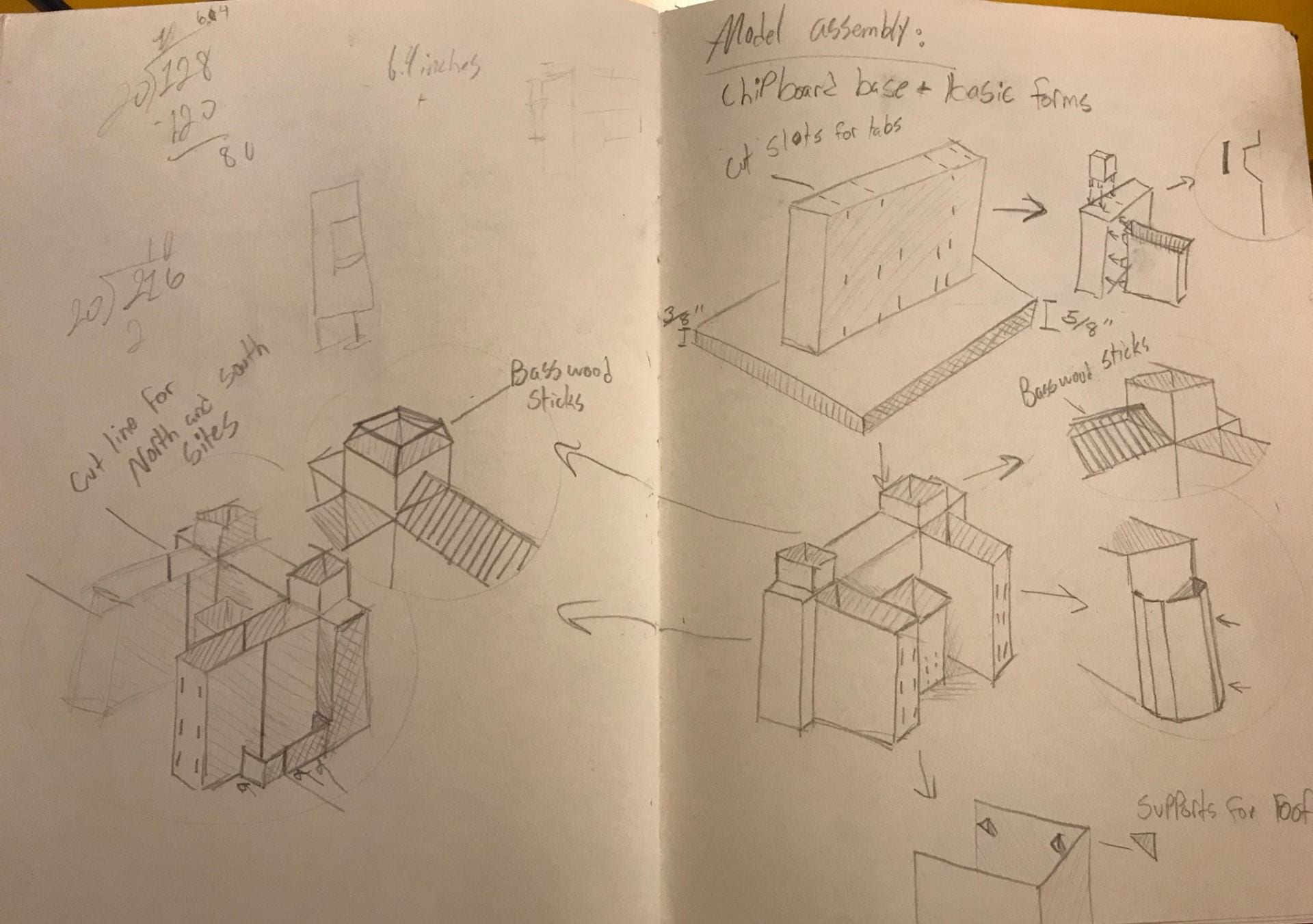
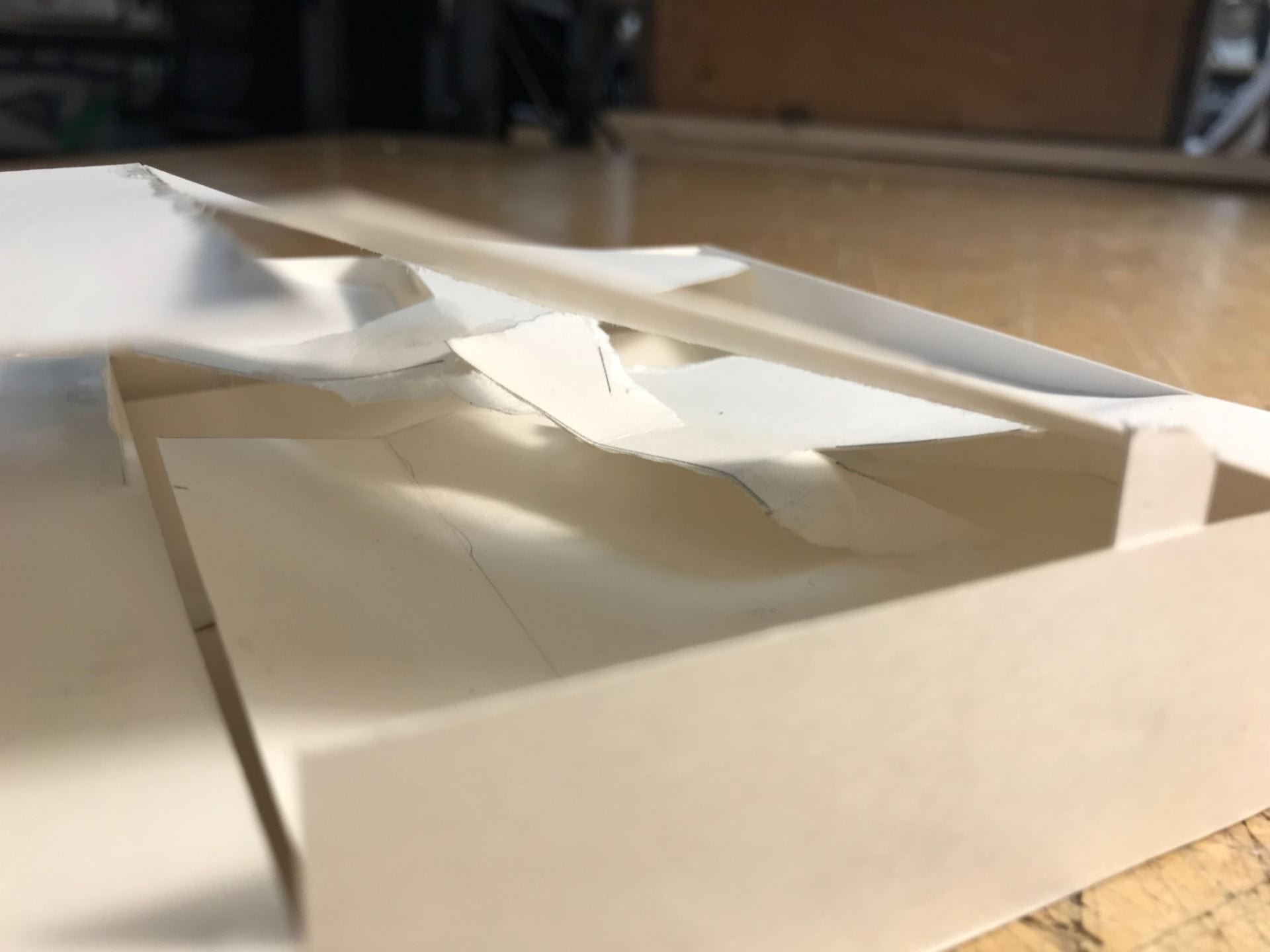
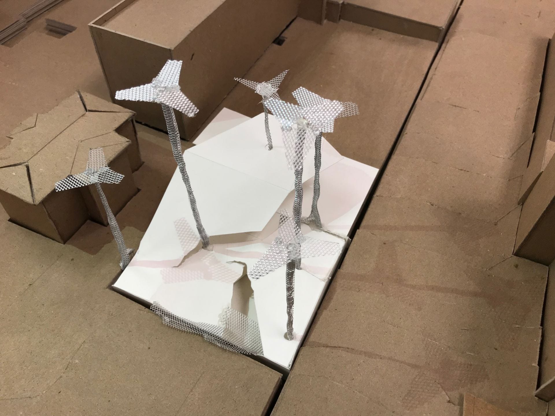
Models
the 1:20 and 1/8″ models were meant to act as supplements to one another
1:20 model
Photos of the 1:20 model were taken at angles associated with the site
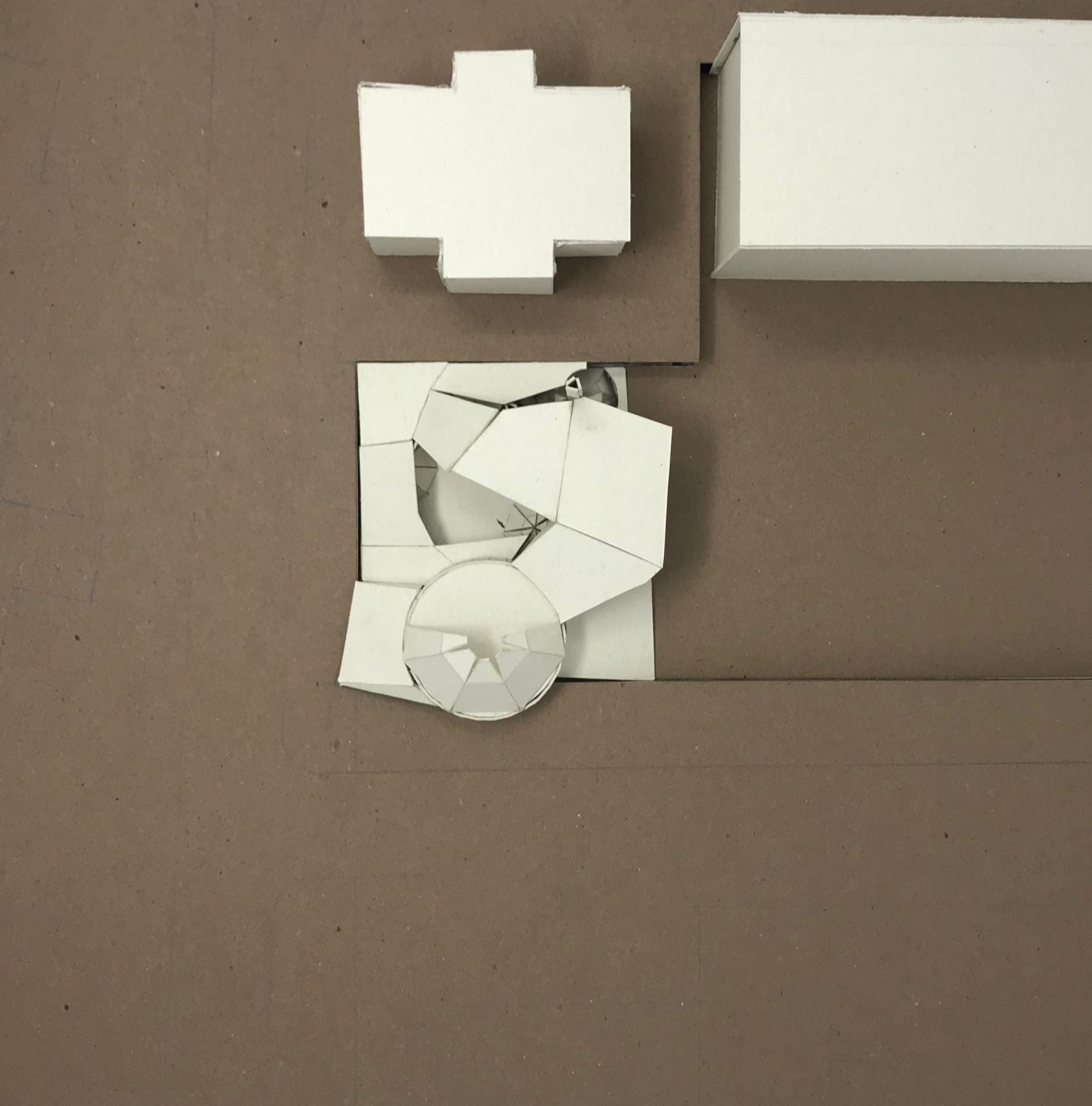
Aerial

From Auburn Place sidewalk
From sidewalk level access, looking towards front entrance

view of outdoor performance stage from outdoor seating platform

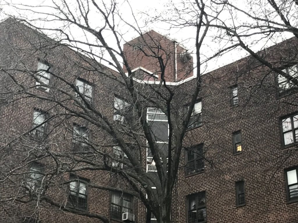
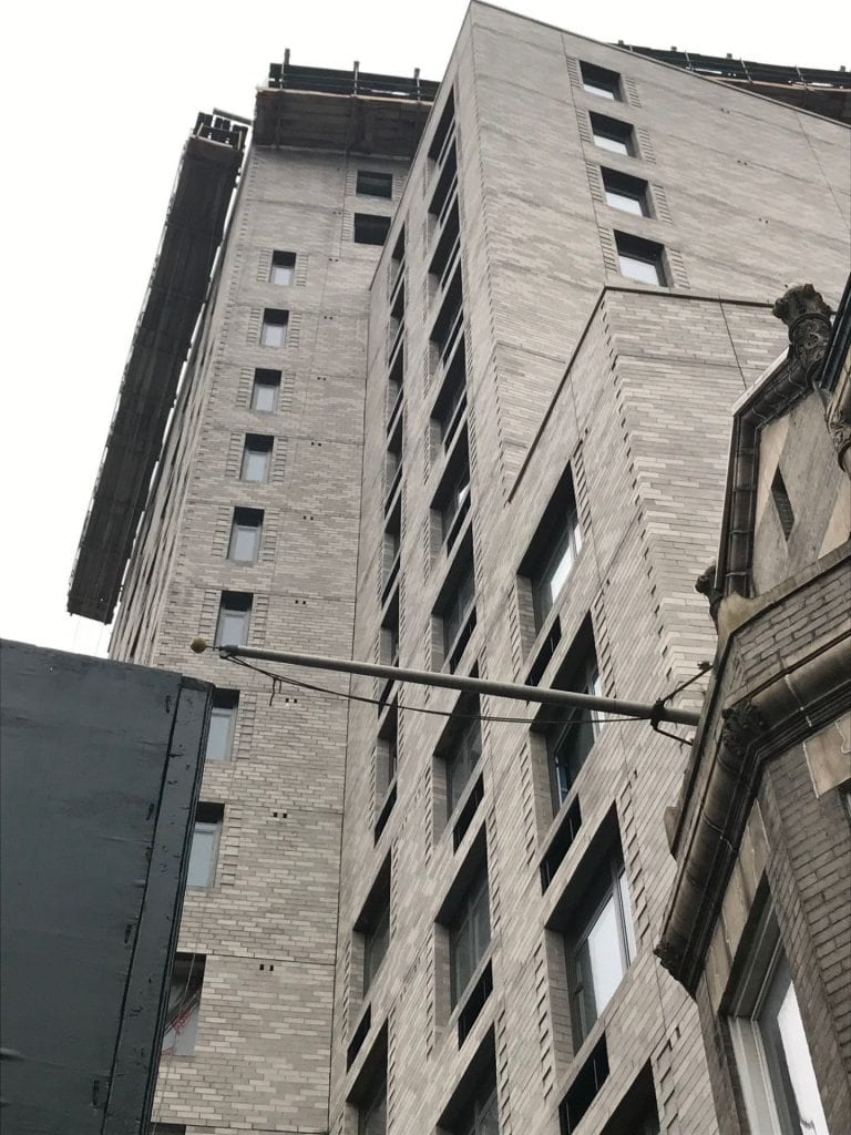
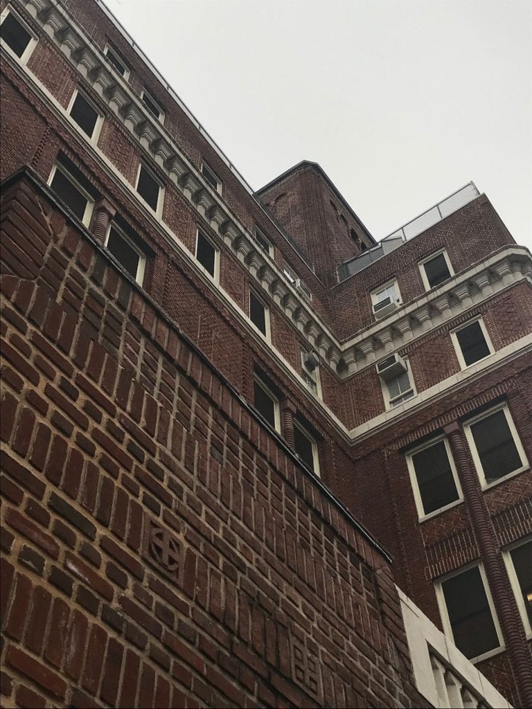
View from a room in an eastern part of the Ingersoll complex across from the site

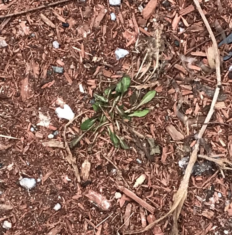
view from playground

view from further into the playground

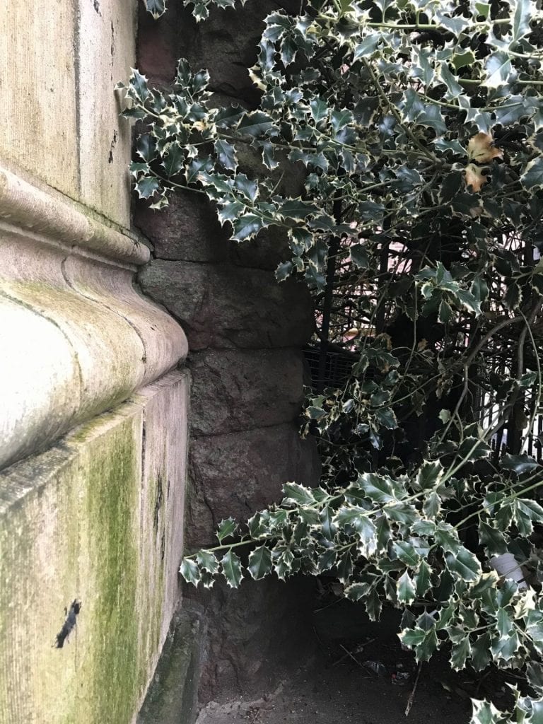
view from walkway passing the school playground

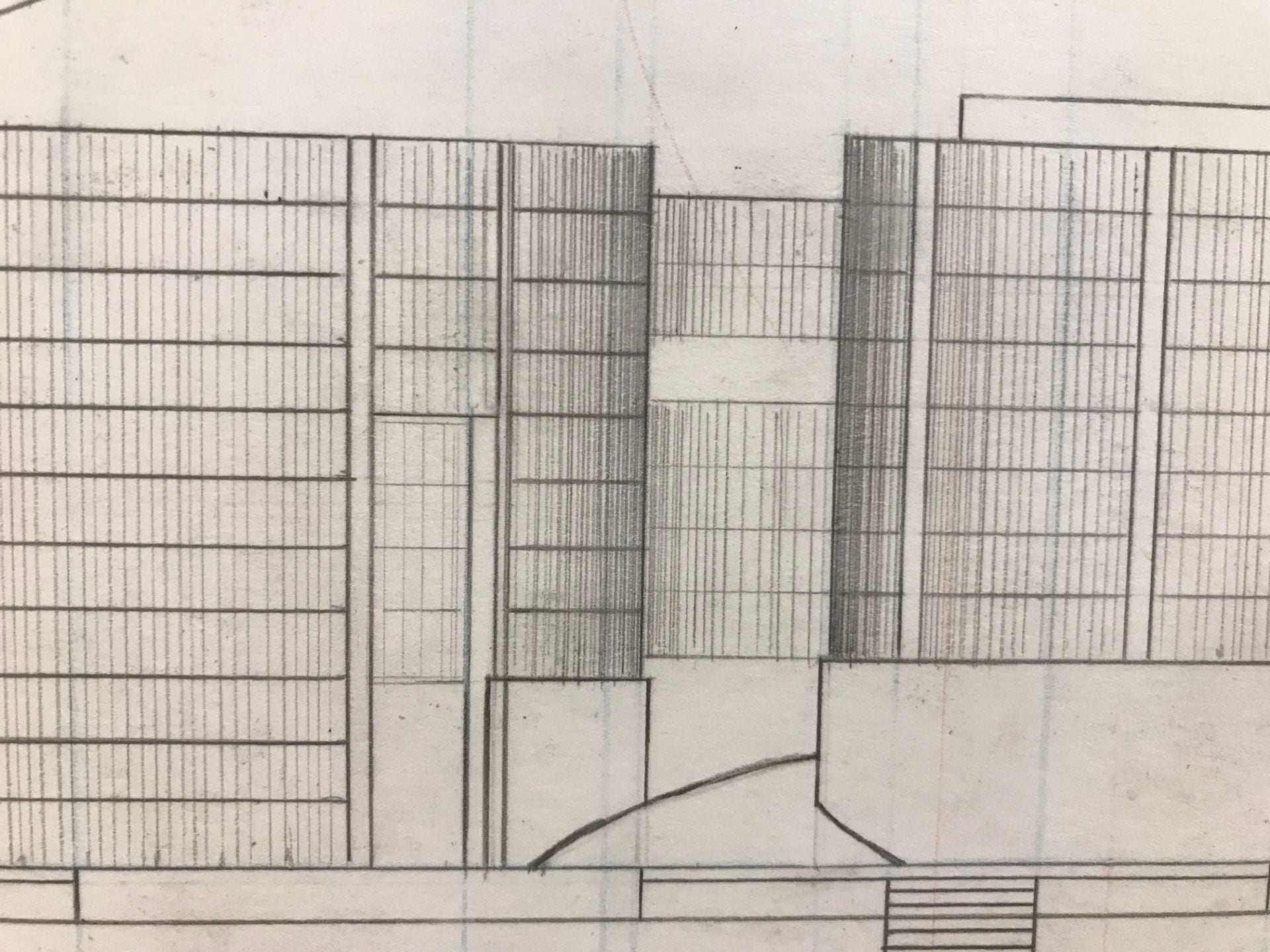
view at the entrance of playground access slope into potluck space. note: areas that are open are not enclosed because of the spatial quality created by the “parted wood” system on the roof of the structure. This allows for light to pass through the side facing south, which flows into the public potluck space.

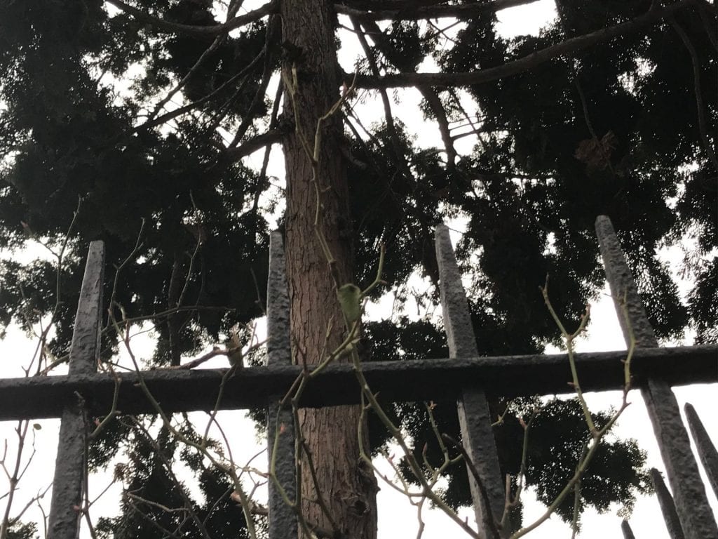
view from sidewalk+stairs that lead into the playground
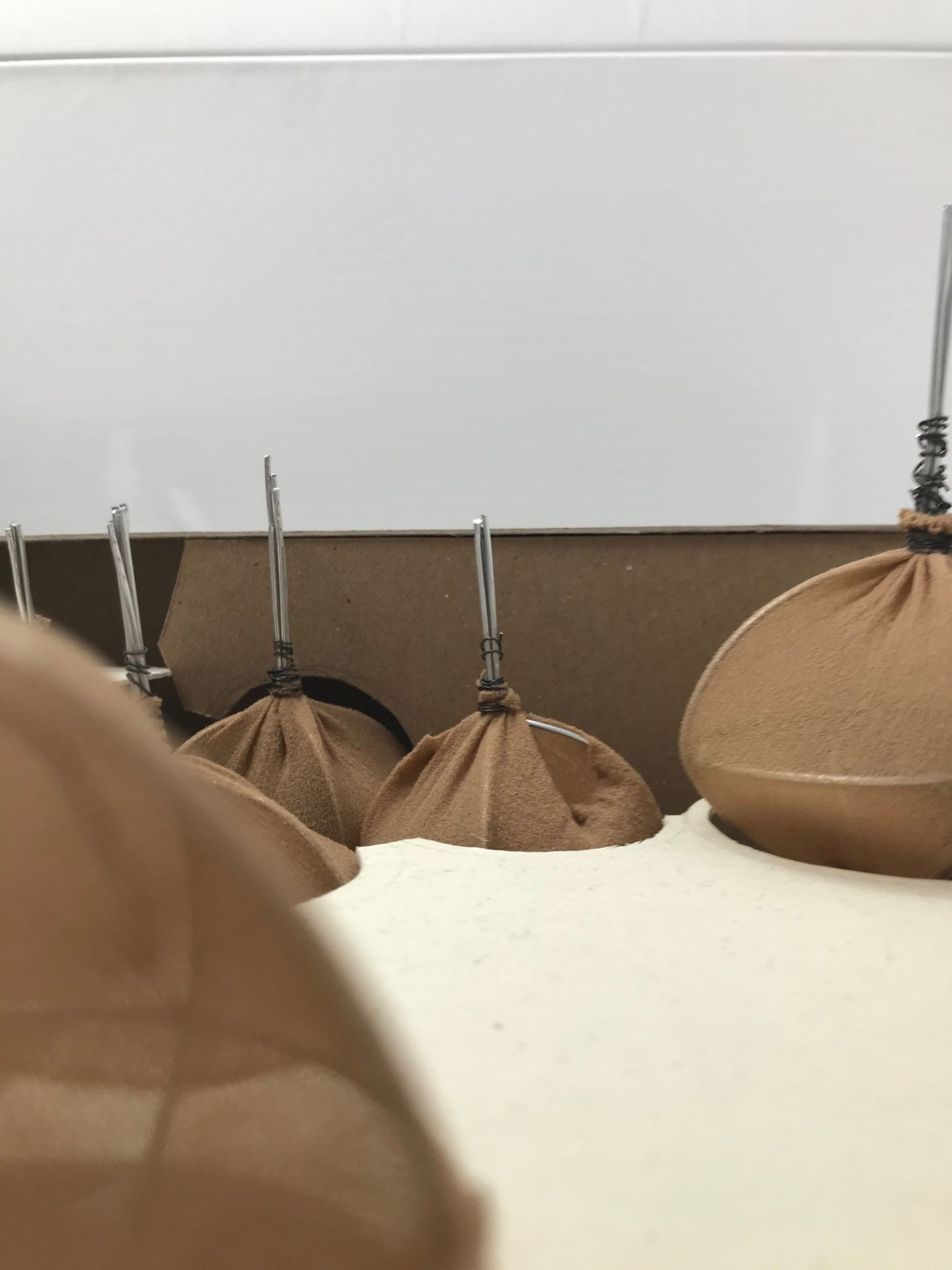
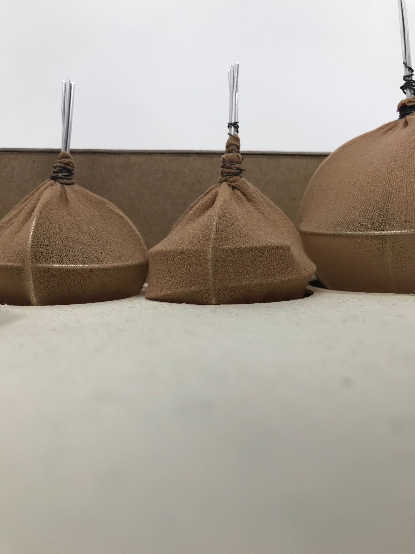
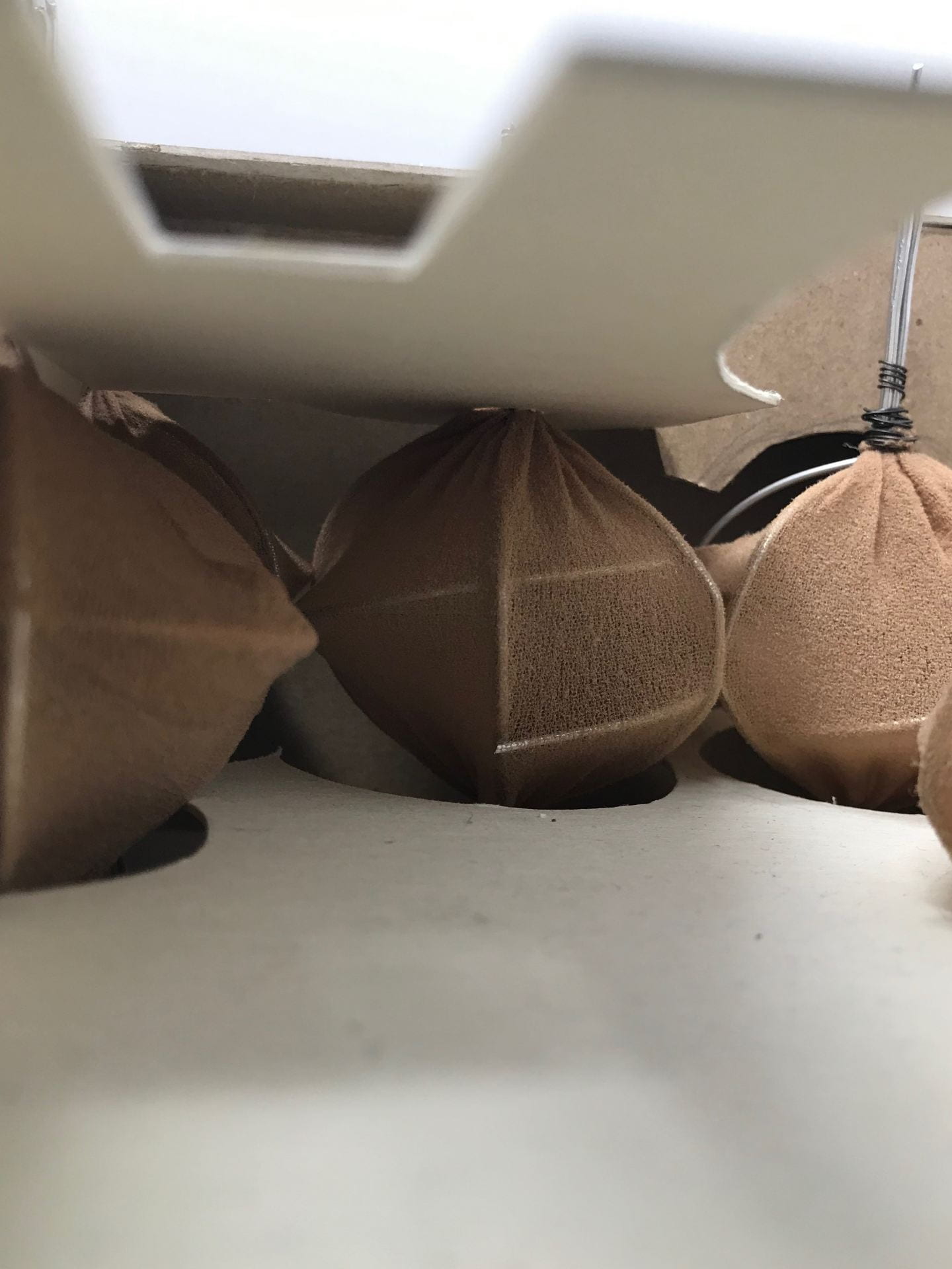
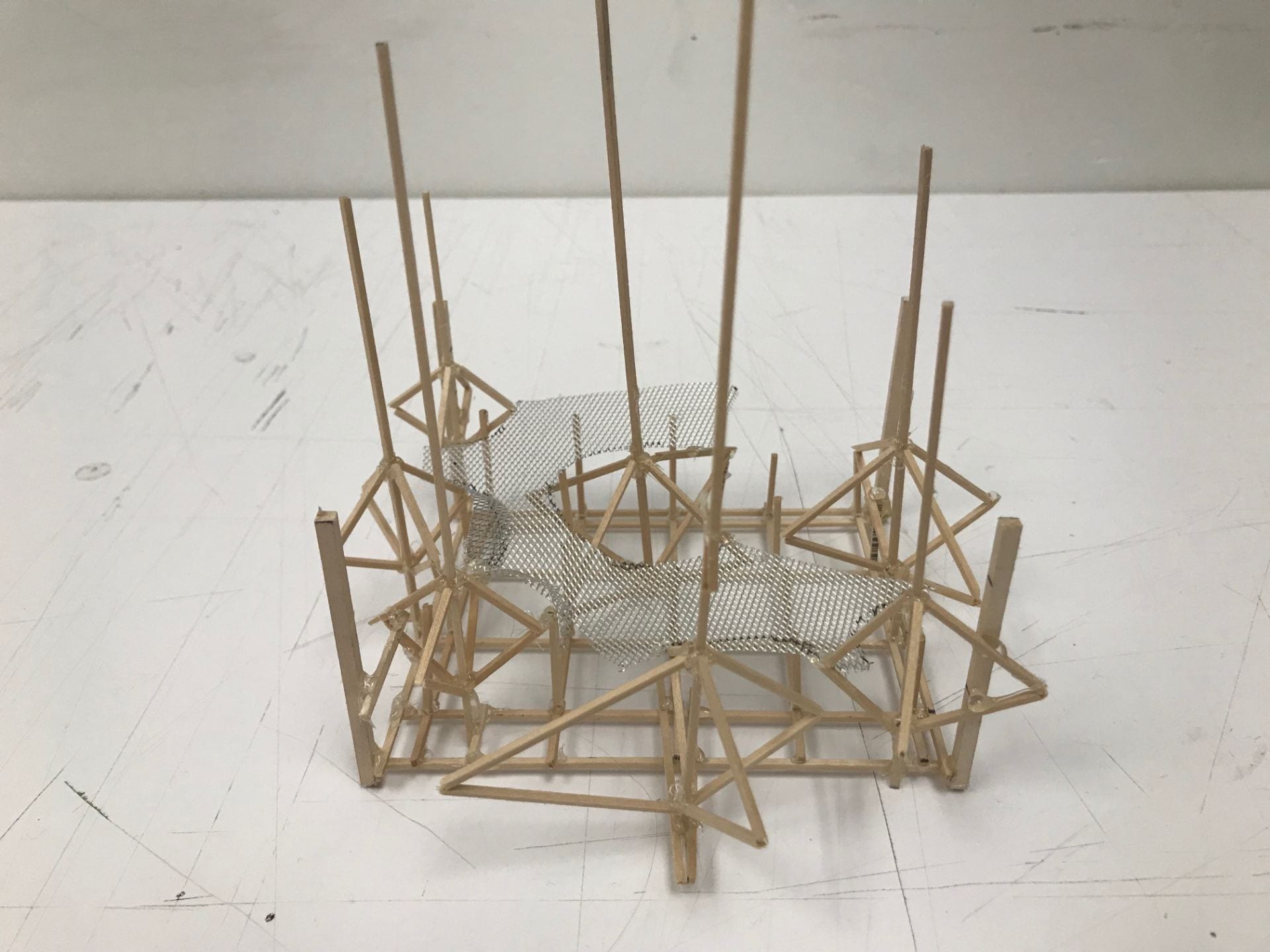
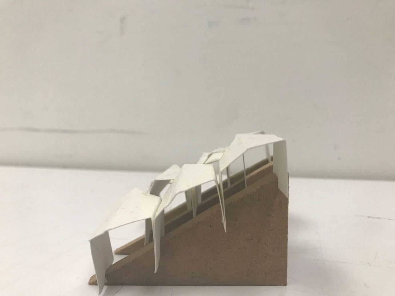
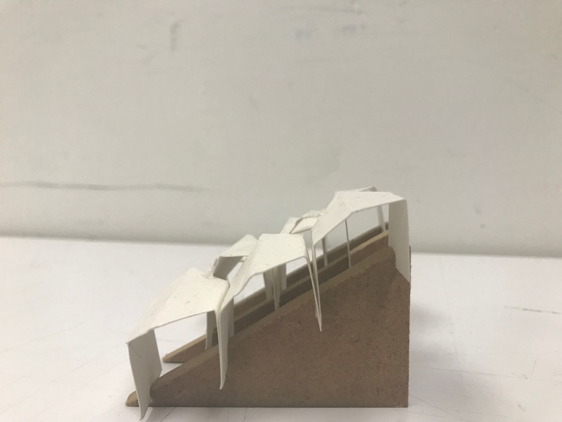
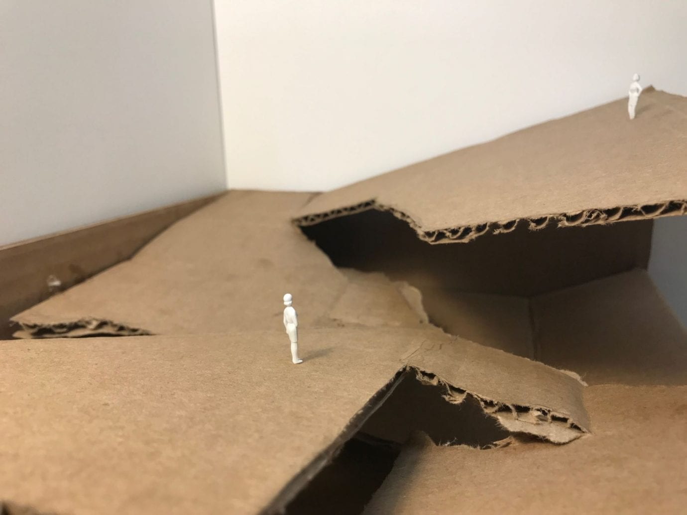
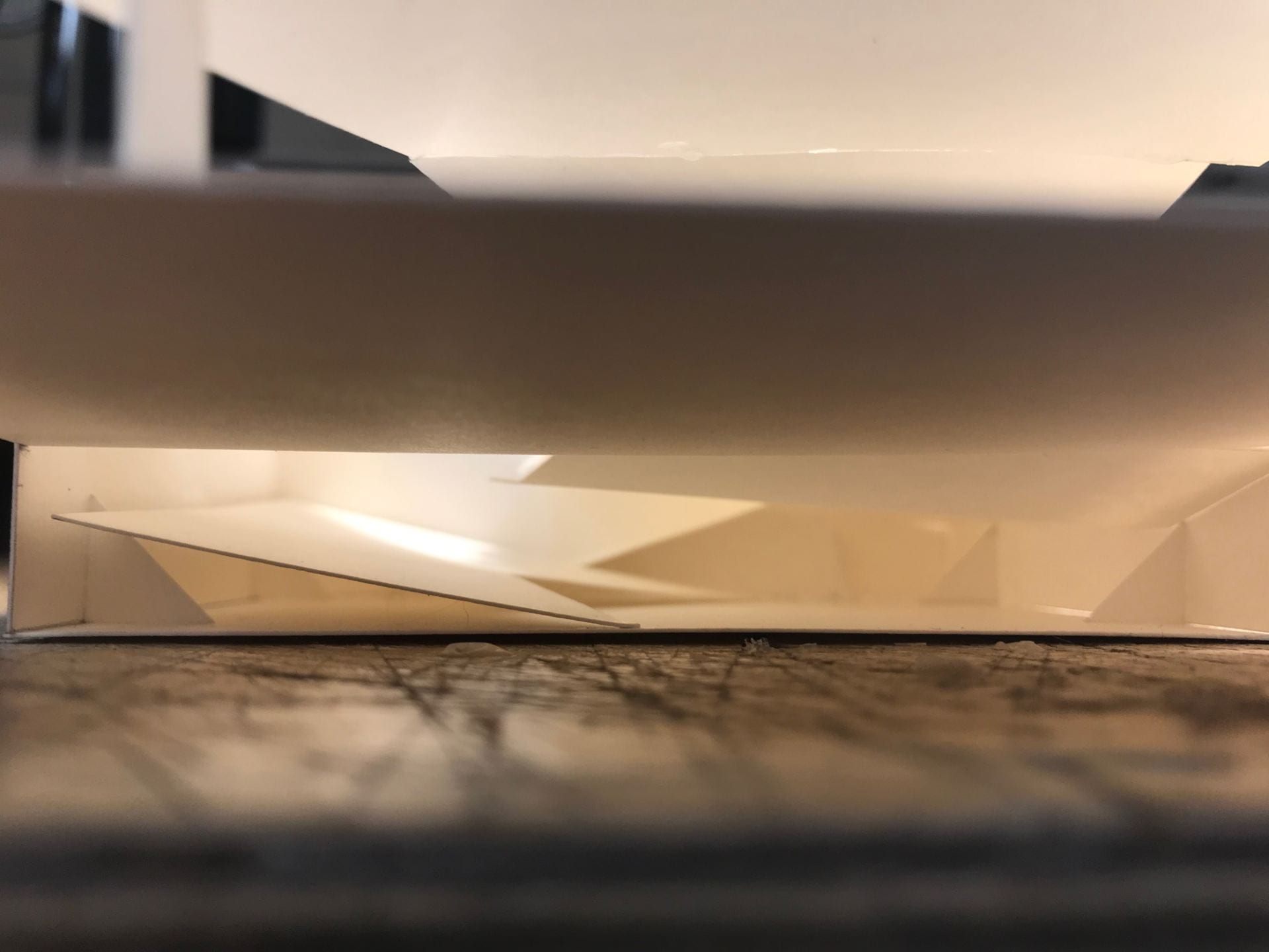
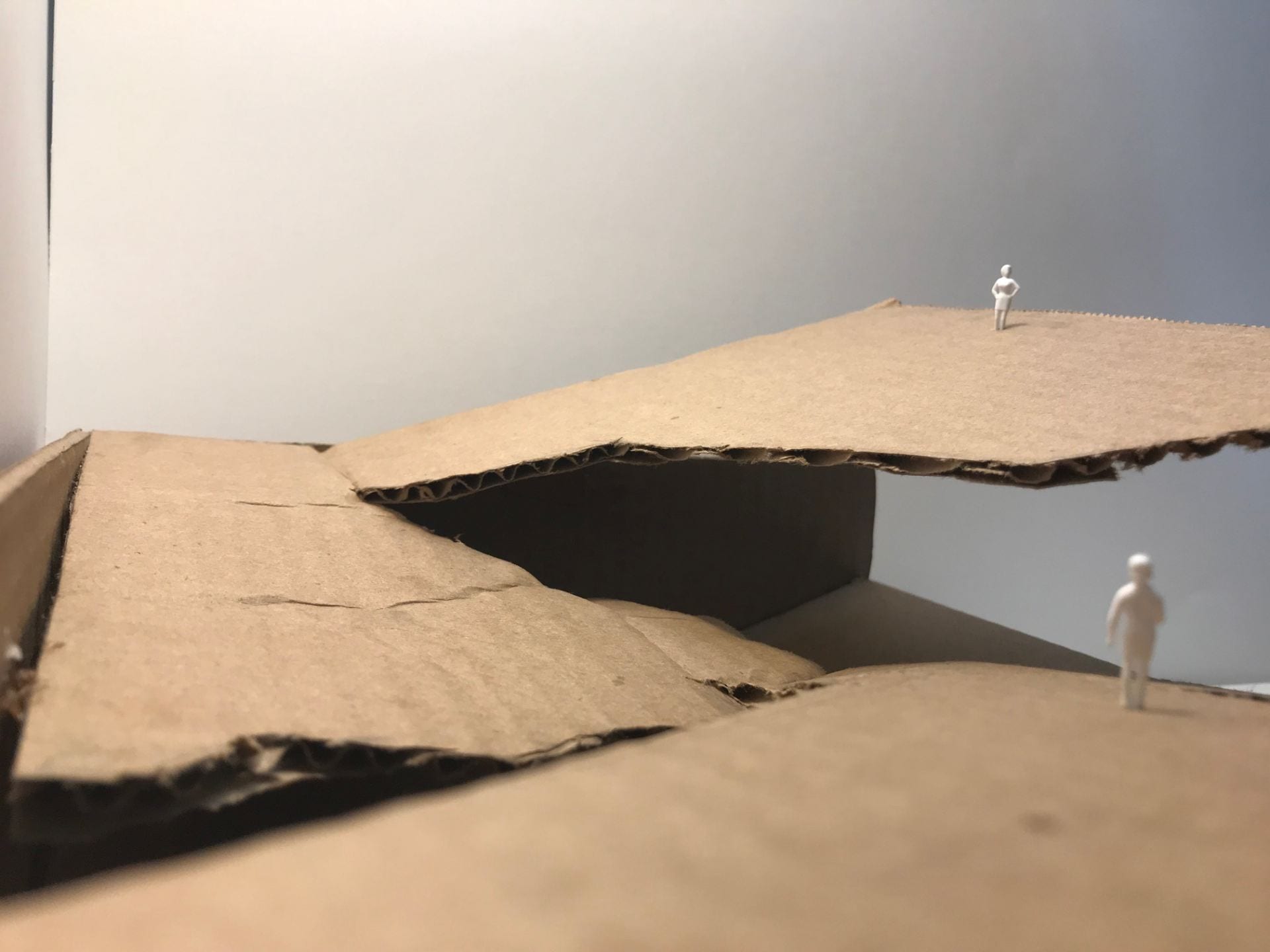
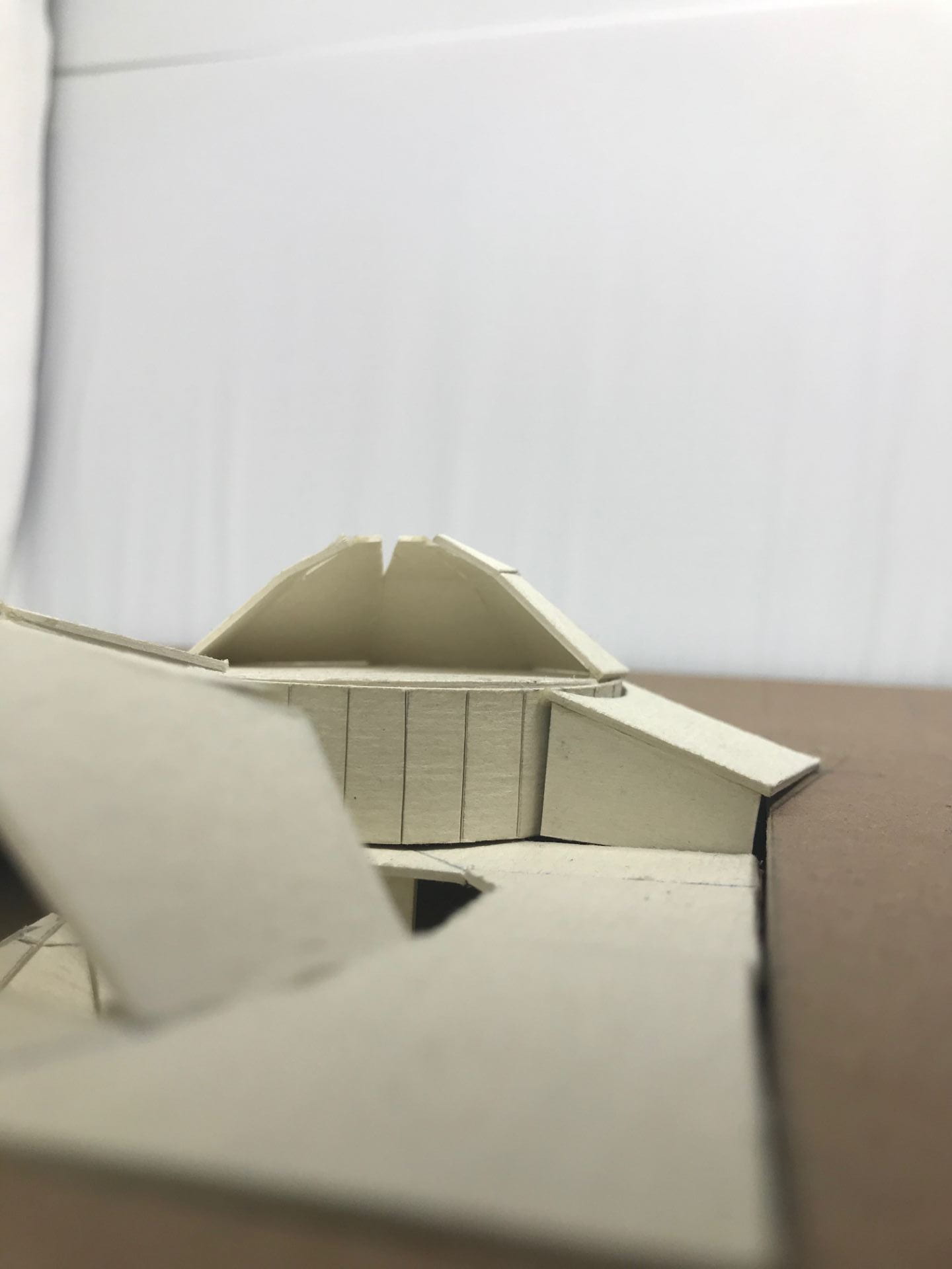
1/8″ model
This model highlights the spatial quality of the area below the roof, where a large portion of the program takes place: